3-5
Cisco SCE8000 GBE Installation and Configuration Guide
Chapter 3 Cisco SCE 8000 Topology and Topology-Related Parameters
Cisco SCE 8000 Interface Numbering
Single Link: Inline Topology
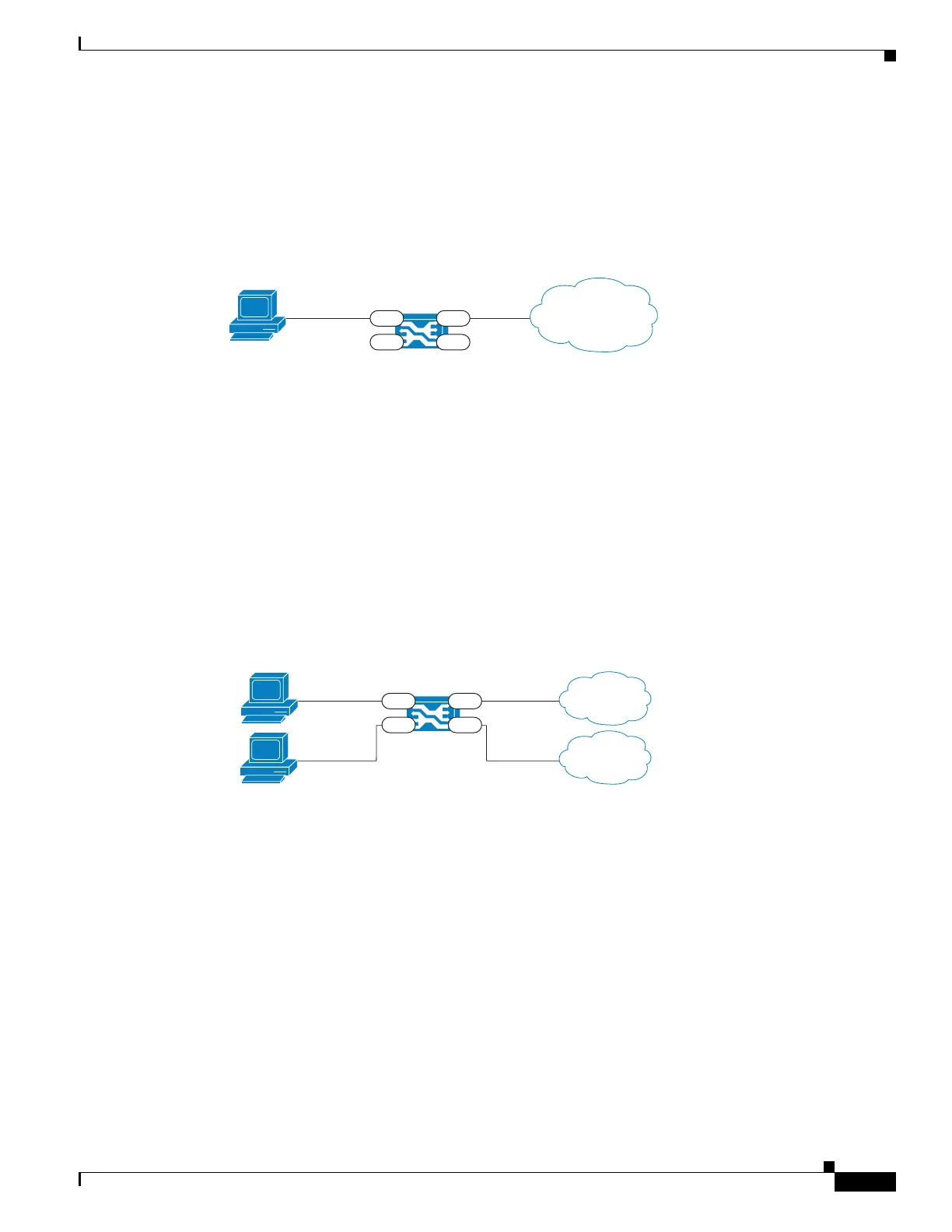
Typically, the Cisco SCE 8000 is connected in a full duplex 10 GBE link between two devices (Router,
BRAS, and so on). When the Cisco SCE 8000 is installed as an inline installation, it physically resides
on the data link between the subscribers and the network (see Figure 3-2).
Figure 3-2 Single Link: Inline Topology
When configuring the Cisco SCE 8000, an inline installation is referred to as “inline” connection mode.
Dual Link: Inline Installation
In this topology, one Cisco SCE 8000 is connected inline in two full duplex, 10 GBE links (see
Figure 3-3).
In case the two links are load-shared, asymmetrical routing might occur, and some of the flows may be
split, that is, the upstream packets of the flow go on one link, and the downstream packets go on the other
link.
When installed in this topology, the Cisco SCE 8000 completely overcomes this phenomenon, and
provides its normal functionality as if asymmetrical routing were not occurring in the two links.
Figure 3-3 Dual ink: Inline Installation
This topology supports both monitoring and control functionality, and is referred to as “inline”
connection mode.
Subscriber
270588
Network
3/0/0
3/2/0
3/1/0
3/3/0
Subscriber 1
270589
Network 1
3/0/0
3/2/0
3/1/0
3/3/0
Subscriber 2
Network 2