4-12
Cisco SCE8000 GBE Installation and Configuration Guide
Chapter 4 Installing the Cisco SCE 8000 Chassis
DC-Powered Systems
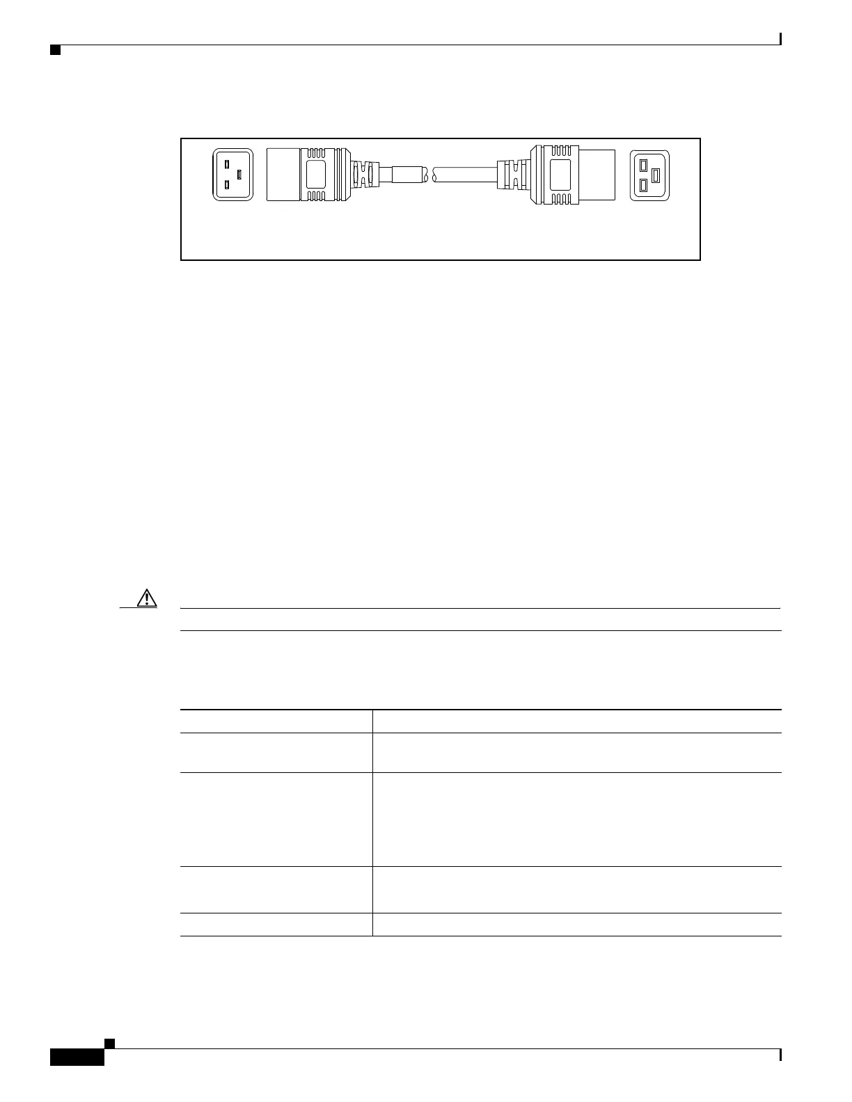
Figure 4-12 CAB-C19-CBN
DC-Powered Systems
Basic guidelines for DC-powered systems include the following:
• Each chassis power supply should have its own dedicated input power source. The source must
comply with the safety extra-low voltage (SELV) requirements in the UL 60950, CSA 60950, EN
60950, and IEC 60950 standards.
• The DC supplies each have the provision for a dual connection to the power source in order to permit
high-power operation without exceeding current ratings. For the Cisco SCE 8000, it is not necessary
to connect both of these inputs to DC power sources; it is sufficient to connect only the '1'
connections.
• Each circuit must be protected by a dedicated two-pole circuit breaker. The circuit breaker should
be sized according to the power supply input rating and local or national code requirements.
• The circuit breaker is considered the disconnect device and should be easily accessible.
• The system ground is the power supply and chassis ground.
Caution Do not connect the DC-return wire to the system frame or to the system grounding equipment.
Table 4-5 lists the Cisco SCE 8000 DC power specifications.
Cordset rating: 16 A, 250 V
Length: 9 ft 0 in. (2.7 m)
140587
Connector:
IEC 60320 C19
Connector:
IEC 60320 C20
Table 4-5 Cisco SCE 8000 DC Power Supply Specification
Specification Acceptable Range
PWR-2700-DC/4 minimum
capability
1350 W output (1750 W input)
DC-input power consumption
• Single Cisco SCE 8000-SCM-E module:
1000 W (21 A @ 48 VDC, 17 A @ 60 VDC)
• Dual Cisco SCE 8000-SCM-E modules:
1430 W (30 A @ 48 VDC, 24 A @ 60 VDC)
DC-input voltage rating -48 VDC to -40 VDC
(operating range: -40.5 VDC to -72 VDC)
DC-input current rating 45 A maximum at 120 VAC