4-21
Cisco SCE8000 GBE Installation and Configuration Guide
Chapter 4 Installing the Cisco SCE 8000 Chassis
Required Tools and Equipment
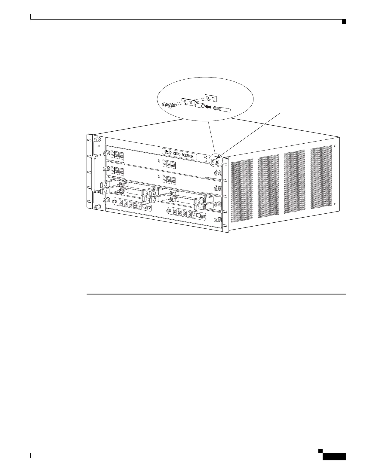
Step 4 Locate and remove the adhesive label from the system grounding pad on the chassis. (See Figure 4-16.)
Figure 4-16 Installing the System Ground
Step 5
Place the grounding wire lug against the grounding pad, making sure there is solid metal-to-metal
contact.
Step 6 Secure the grounding lug to the chassis with two M4 screws. Ensure that the grounding lug will not
interfere with other hardware or rack equipment.
Step 7 Prepare the other end of the grounding wire, and connect it to an appropriate grounding point in your
site to ensure adequate earth ground for the Cisco SCE 8000 chassis.
F
AN
STAT
U
S
SCM
1
SCM
2
S
I
P
3
4
S
CE
8
00
0
-FA
N
S
YS
T
EM PO
W
E
R
OP
T
I
C
AL BY
P
A
SS
ST
A
T
U
S
A
U
X
P
O
R
T
2
L
INK
A
C
T
I
V
E
MA
STER
SC
E8
0
0
0
E
X
T
E
N
DE
D
SERVI
C
E
CO
N
TROL
M
O
D
U
L
E
O
PTIC
AL
B
YP
A
S
S
O
P
T
IC
A
L
B
YP
AS
S
C
O
NSO
L
E
1
0
10
0
1
0
0
0
L
INK
A
C
TI
V
E
P
O
R
T1
A
C
A
B
C
D
B
D
S
TA
TUS
C
TR
L
O
PB
-
SC
E8
K
-
MM
O
P
T
I
C
AL
B
YPASS
1
TX
R
X
TX
RX
TX
RX
TX
R
X
A
C
A
B
C
D
B
D
S
T
A
T
U
S
C
T
RL
O
PB-SC
E8
K
-M
M
O
PT
ICA
L
BY
P
A
SS
2
T
X
R
X
T
X
R
X
T
X
R
X
T
X
R
X
S
YS
T
EM
P
O
WER
OPT
I
C
AL
BY
P
A
S
S
ST
A
T
U
S
A
UX
PO
R
T2
1
0
1
00
1
00
0
L
I
N
K
A
C
T
I
V
E
M
AS
T
ER
SC
E8
0
0
0
E
X
T
E
N
DE
D SERVI
C
E
CO
NTROL
M
O
D
U
L
E
S
C
E
8
00
0-
SC
M
-
E
S
C
E
8
00
0-
SC
M
-
E
S
C
E
8
0
00-
S
I
P
C
O
NSO
L
E
1
0
1
00
1
0
0
0
L
INK
A
CTI
V
E
P
O
RT 1
O
P
T
I
C
A
L
B
YP
A
SS
OP
TIC
A
L
B
YPA
S
S
ST
A
T
U
S
A
CT
I
V
E
/
L
IN
K
SP
A-1
X
1
0
G
E
-L
-V
2
ST
A
T
U
S
A
C
T
I
V
E
/
L
I
N
K
SP
A
-1
X
1
0
G
E-L
-V
2
S
T
A
T
US
A
CT
I
V
E
/
LI
N
K
S
P
A-1
X
1
0
G
E-L
-V
2
ST
A
T
U
S
A
C
T
I
V
E
/
L
I
N
K
S
P
A-1
X
1
0
G
E-L
-
V
2
1
0
1
00
1
0
00
270892
System ground
connector
System ground
connector
Grounding
lug
Wire