DC power input13Status LED for FXS RJ-21 connector 13
USB connector14Status LED for CompactFlash card4
RJ-45 serial AUX port15CompactFlash card slot5
Mini USB connector16Status LED for mini USB6
EHWIC slot17Status LED for console7
FXS RJ-21 connector 218RJ-45 serial console port8
Status LED for FXS RJ-21 connector 219Gigabit Ethernet ports (2)9
Status LEDs for DC input power10
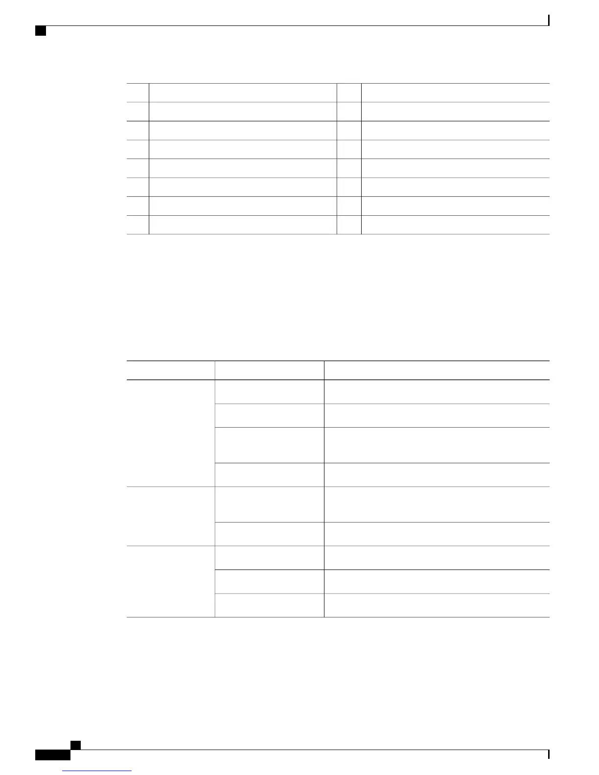
LED Indicators
The following table summarizes the LED indicators that are located on the chassis of both VG310 and VG320,
but not on the removable modules or interface cards.
For descriptions of LEDs in removable modules and interface cards, see the applicable documentation for
those products.
Table 2: Cisco VG310 and Cisco VG320 LED Indicators
DescriptionColorLED
Normal operation. System is receiving power.GreenSYS
Operating system boot up in progress.Blinking green
Power supply is available, but the unit has an error
condition.
Amber
System is not receiving power.Off
Indicates packet activity between the forwarding and
routing engine and an I/O port.
GreenACT
No packet transfers are occurring.Off
PVDM3 is detected and enabled.GreenPVDM
PVDM3 is detected, but has an error condition.Amber
PVDM3 is not installedOff
Cisco VG310 and Cisco VG320 Voice Gateways Hardware Installation Guide
6 OL-31292-01
Overview of the Cisco VG310 and Cisco VG320 Voice Gateways
Physical Description and LEDs