3-5. Disassembly, Reassembly and Lubrication
CLP-621 & CLP-631 3-32
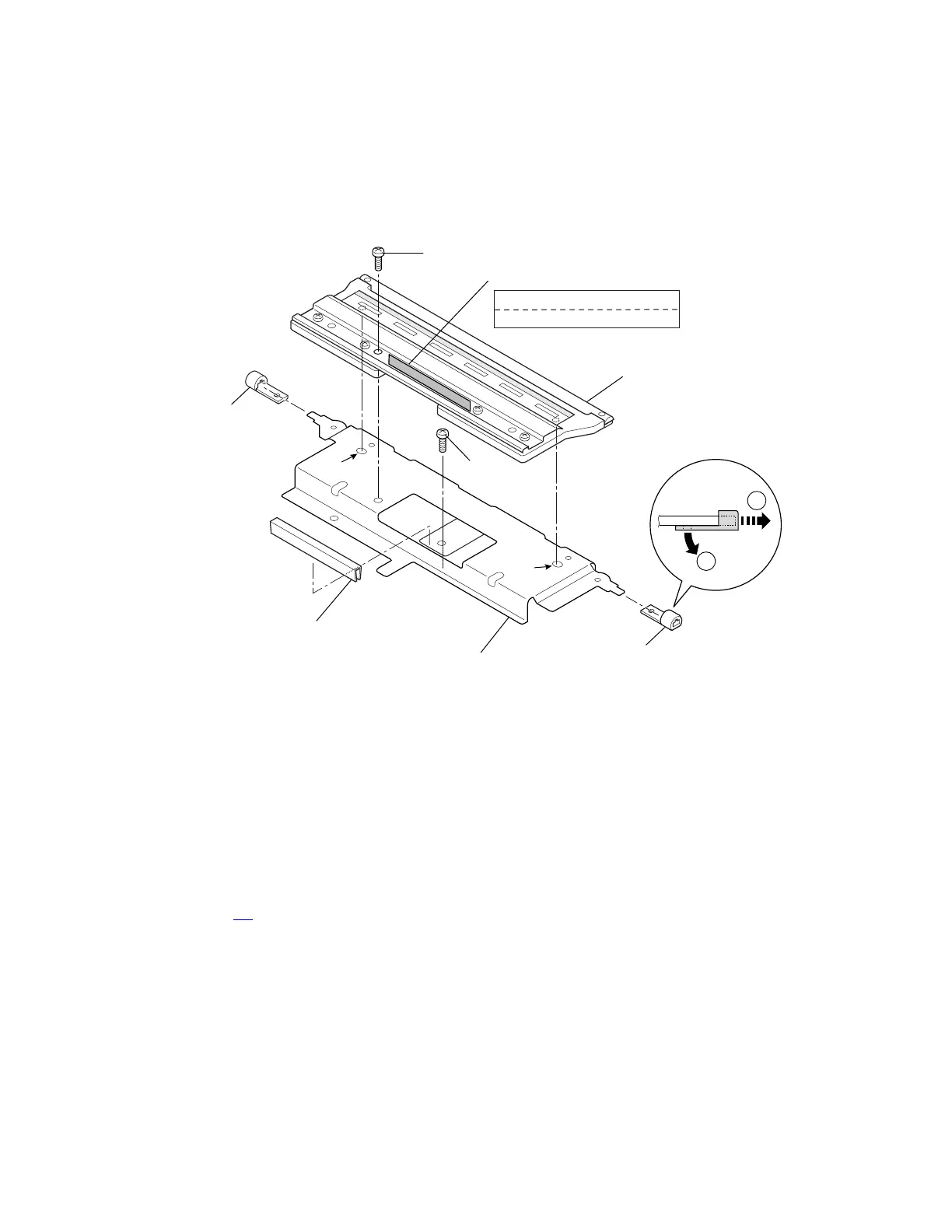
(2) Head SA
1. Remove the Head Unit. Refer to (1) “Head Unit” as above.
2. Remove 1 screw (BH (N), M3x6) and detach the Head SA.
3. Remove 2 Head Bushings, 1 screw (PH, M3x8) and Head Connector Guard from the Head
Bracket.
(The screw (PH, M3x8) is used for alignment purpose and not for mounting.)
1
2
E
PH, M3x8
Bracket, Head
Bushing, Head
Bushing, Head
Guard, Head Connector
SA, Head
E
Label, Part Number
White Label for CLP-621
Yellow Label for CLP-631
BH (N), M3x6
Notes on reassembling:
• When assembling the Head SA, insert its 2 protrusions into the guide holes “E” for aligning
and then fix the Head SA with 1 screw.
• After assembling the Head SA, clean the surface of the thermal elements with the head
cleaner.
• After assembling the Head SA, perform test print in self print mode to check the print quality.
(Refer to 2-3-2-(2-1) “Self print mode”.) If the print quality is not enough, ribbon slanting or
ribbon wrinkle may occur. In this case, perform 3-6-2 “Ribbon Slant Elimination Adjustment”
on page 3-
45.