3-5. Disassembly, Reassembly and Lubrication
3-35 CLP-621 & CLP-631
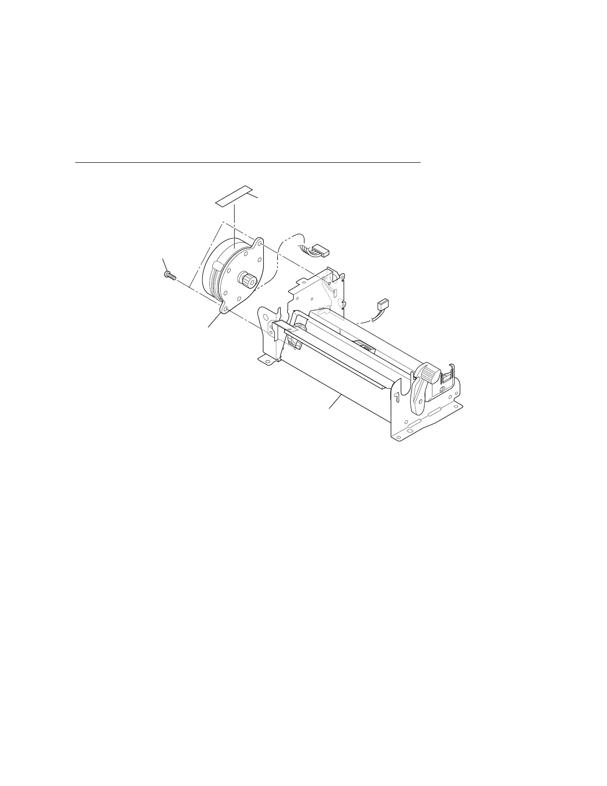
3-5-20. Motor SA
1. Remove the Mechanism Unit. Refer to 3-5-13 “Mechanism Unit and Case L”.
2. Remove 2 screws (PH, M3x3), and detach the Motor Block. Then, peel off the Caution Head
Label 5 from the Motor SA.
Note on reassembling:
•
Once the Caution Head Label 5 has been removed, it cannot be reused.
(Unit, PF)
SA, Motor
PH, M3x3
Label 5, Caution Head
3-5-21. Reflective Sensor PCB SA
1. Remove the Mechanism Unit. Refer to 3-5-13 “Mechanism Unit and Case L”.
2. By accessing to the connector of the Reflective Sensor Cable SA from the bottom, disconnect
it from the Reflective Sensor PCB SA.
3. Open the Head Block, remove 1 screw (PH, M3x6), and detach the Guide Sensor L Holder.
4. Slide the Paper Set Guide to the left (c) and remove the Sensor Guide Shaft in the direction
shown by the arrow (d), together with the Paper Set Guide and Sensor Holder L SA.
5. Pull out the Paper Set Guide from the Sensor Guide Shaft and remove the attached Sensor L
Damper and the Paper Set Sheet.
6. Pull out the Sensor Holder L SA from the Sensor Guide Shaft and remove the attached Sensor
L Damper and the Paper Set Sheet.
7. Remove 1 screw (NO.0 PHT (BT#1), M2x3) and detach the Reflective Sensor PCB SA from
the Sensor Holder L SA.
8. Cut 2 Wire Ties and remove the Reflective Sensor Cable SA.