3-5. Disassembly, Reassembly and Lubrication
CLP-621 & CLP-631 3-36
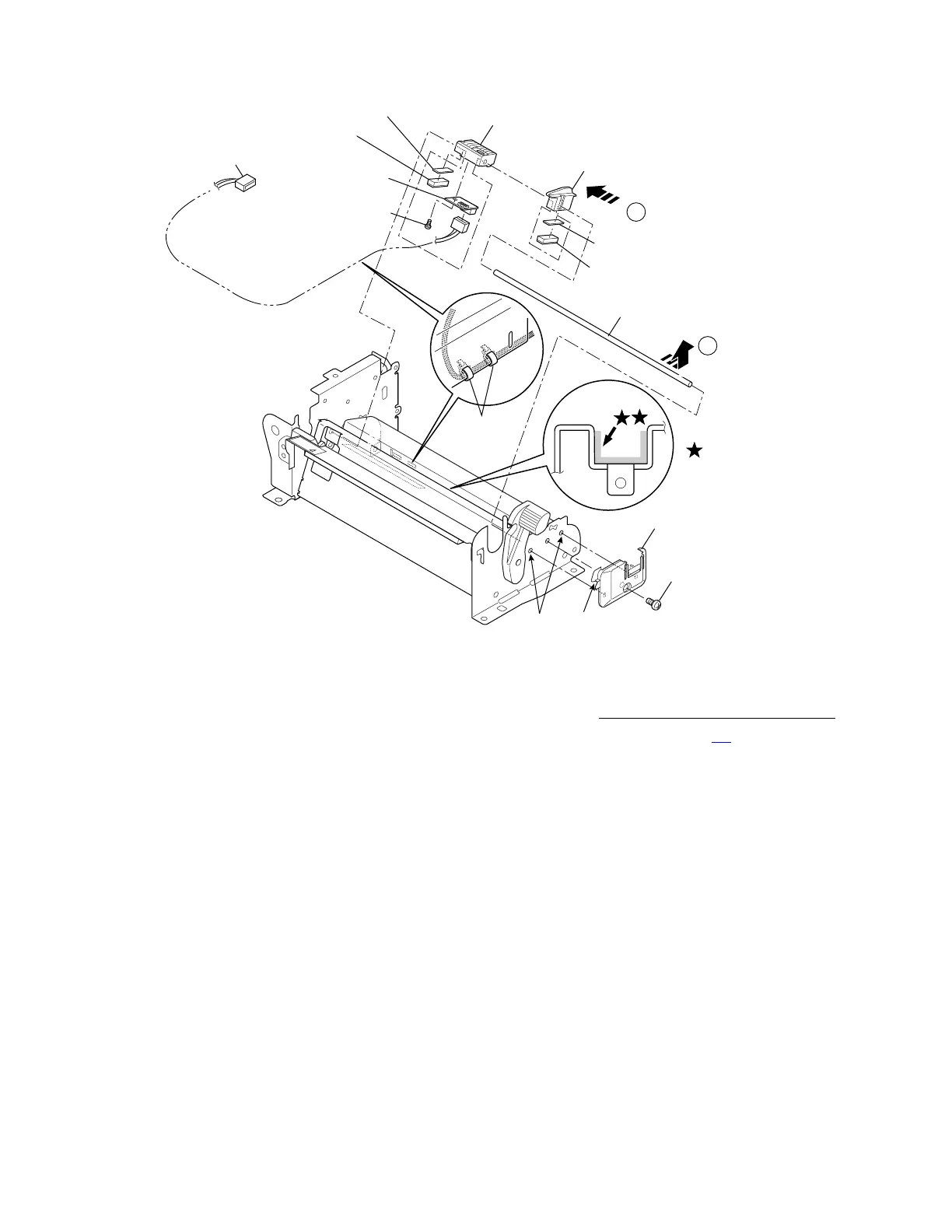
PH, M3x6
Holder, Guide Sensor L
Guide, Paper Set
SA, Sensor Holder L
Shaft, Sensor Guide
Damper, Sensor L
Damper, Sensor L
SA, Reflective
Sensor PCB
NO.0 PHT (BT#1), M2x3
SA, Reflective
Sensor Cable
Wire Ties
A
B
Sheet, Paper Set
Sheet, Paper Set
FLOIL G-311S
1
2
Notes on reassembling:
• When the Reflective Sensor PCB SA is replaced with new one,
perform the sensor adjustment.
Refer to 3-6-1 “Transparent/Reflective Sensor Position Adjustment” on page 3-
40.
• Apply Floil G-311S along the groove of the frame as shown.
• When assembling the Sensor L Damper, push it so that the felt side can be seen.
• Assemble the Sensor Guide Shaft (with the Sensor Holder L SA and the Paper Set Guide), and
align its ends in places. Next, securely assemble the Guide Sensor L Holder. (The groove “A” of
the Guide Sensor L Holder should engage in the frame plate and also the protrusions should be
inserted into the holes “B” on the frame.)
• When assembling the Reflective Sensor Cable SA, bind it with 2 Wire Ties as shown.