3-5. Disassembly, Reassembly and Lubrication
3-15 CLP-621 & CLP-631
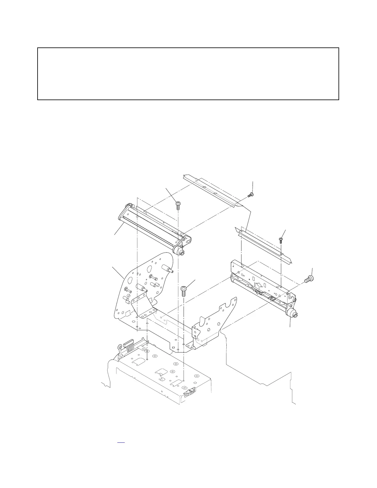
3-5-7. Ribbon Sensor F/R Unit and Ribbon Unit Base Plate SA1
Caution:
DO NOT disassemble the Ribbon Unit Base Plate SA1, though it consists of three parts.
If it
is disassembled, correct ribbon running cannot be assured. Namely, ribbon slant
correction may become impossible within the adjustable range o
f the Ribbon Left-Right
Balance Adjustment Knobs (Front/Rear).
1. Open the Top Cover SA.
2. Remove 4 screws (NO.0, TFH, M2x3 (NI)) and detach the Ribbon Tension Adjust Covers on
the front and rear sides.
3. Remove 2 screws (BH, M3x3 (NI)) and detach the Ribbon Sensor F Unit.
4. Remove 2 screws (BH, M3x3 (NI)) and detach the Ribbon Sensor R Unit.
5. Remove 2 screws (PH, M3x6) and detach the Ribbon Unit Base Plate SA1 from the
Mechanism Unit.
(Ribbon Sensor F Unit)
BH, M3x3 (NI)
Cover, Ribbon Tension Adjust
(Ribbon Sensor R Unit)
BH, M3x3 (NI)
NO.0, TFH, M2x3 (NI)
NO.0, TFH, M2x3 (NI)
SA1, Ribbon Unit Base Plate
PH, M3x6
DO NOT DISASSEMBLE.
Note on reassembling:
• When assembling the Ribbon Sensor F/R Unit, perform 3-6-2 “Ribbon Slant Elimination
Adjustment” on page 3-
45.