3-5. Disassembly, Reassembly and Lubrication
CLP-621 & CLP-631 3-16
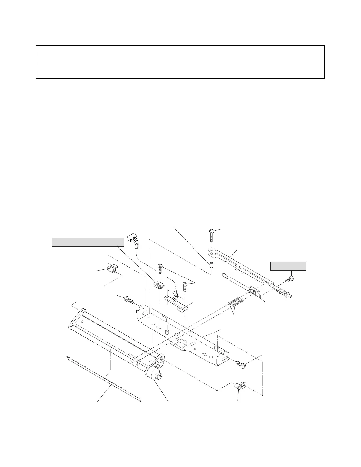
3-5-8. Ribbon Tension Shaft F SA and Tension Sensor SA
Caution:
DO NOT disassemble the Tension Base Adjust Cam and tension adjust screw (PH,
M1.7x4) unless you need to replace them.
1. Open the Top Cover SA.
2. Remove the Ribbon Sensor F Unit. Refer to 3-5-7 “Ribbon Sensor F/R Unit”.
3. Remove 2 screws (NO.0, TFH (BT), M2x4 (NI)) at both ends, and detach the Ribbon Tension
Shaft F SA and Ribbon Guide Roller Bush 2 (2 pcs.).
4. Peel off the Static Eliminator Sheet from the Ribbon Tension Shaft F SA.
5. Remove 1 screw (PH (PW), M2x8), and detach the Tension Adjust Lever F Block and Tension
Adjust Shaft.
6. Remove the Ribbon Sub Adjust Lever F SA and Ribbon Tension Spring F (2 pcs.) from the
Tension Adjust Lever F SA.
7. Remove the tension adjust screw (PH, M1.7x4) from the Tension Adjust Lever F SA.
Note: Do not remove this tension adjust screw unless you need to replace it.
8. Remove 2 screws (NO.0, TFH, M2x3 (NI)) and detach the Tension Sensor SA.
9. Remove 1 screw (NO.0, TFH, M2x3 (NI)), and detach the Tension Base Adjust Cam from the
Ribbon Sensor Frame F SA.
Note: Do not remove the Tension Base Adjust Cam unless you need to replace it.
Cam, Tension Base Adjust
Bush 2, Ribbon
Guide Roller
Bush 2, Ribbon Guide RollerSA, Ribbon Tension Shaft F
Sheet, Static Eliminator 621
NO.0, TFH (BH),
M2x4 (NI)
NO.0, TFH (BH),
M2x4 (NI)
SA, Ribbon Sensor Frame F
Spring F, Ribbon Tension
SA, Ribbon Sub
Adjust Lever F
SA, Tension Adjust Lever F
SA, Tension
Sensor
NO.0, TFH,
M2x3 (NI)
PH (PW), M2x8
PH, M1.7x4
Shaft, Tension Adjust