3-5. Disassembly, Reassembly and Lubrication
3-17 CLP-621 & CLP-631
Notes on reassembling:
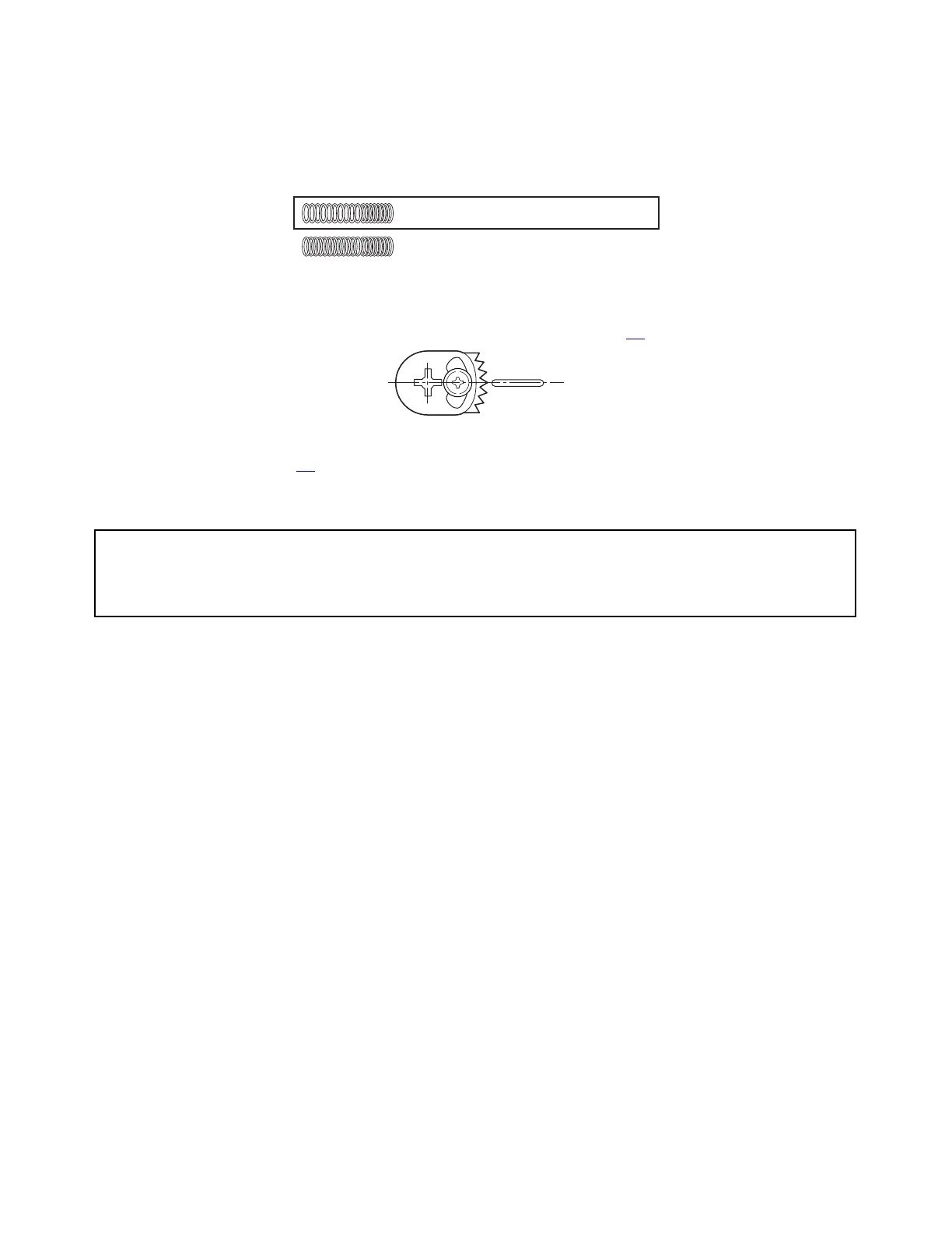
• Distinguish the Ribbon Tension Spring F (used here) and the Ribbon Tension Spring R (used in
the next 3-5-9 “Ribbon Tension Shaft R SA”). They look like the same, but the number of turns
differs.
18 turns (Spring F, Ribbon Tension)
20 turns (Spring R, Ribbon Tension)
• When assembling the Tension Base Adjust Cam, adjust its position as shown in the figure to set
it at the mechanical center. Then, perform adjustment according to 3.6.2-(2-1) “Tension base
adjust cam position adjustment (For service personnel)” on page 3-
47.
• When assembling the tension adjust screw (PH, M1.7x4), perform 3-6-3 “Ribbon Tension
Adjustment” on page 3-
52.
3-5-9. Ribbon Tension Shaft R SA and Tension Sensor SA
Caution:
DO NOT disassemble the Tension Base Adjust Cam and tension adjust screw (PH,
M1.7x4) unless you need to replace them.
1. Open the Top Cover SA.
2. Remove the Ribbon Sensor R Unit. Refer to 3-5-7 “Ribbon Sensor F/R Unit”.
3. Remove 2 screws (NO.0, TFH (BT), M2x4 (NI)) at both ends, and detach the Ribbon Tension
Shaft R SA and Ribbon Guide Roller Bush 2 (2 pcs.).
4. Remove 1 screw (PH (PW), M2x8), and detach the Tension Adjust Lever R Block and Tension
Adjust Shaft.
5. Remove the Ribbon Sub Adjust Lever R SA and Ribbon Tension Spring R (2 pcs.) from the
Tension Adjust Lever R SA.
6. Remove the tension adjust screw (PH, M1.7x4) from the Tension Adjust Lever R SA.
Note: Do not remove this tension adjust screw unless you need to replace it.
7. Remove 2 screws (NO.0, TFH, M2x3 (NI)) and detach the Tension Sensor SA.
8. Remove 1 screw (NO.0, TFH, M2x3 (NI)), and detach the Tension Base Adjust Cam from the
Ribbon Sensor Frame R SA.
Note: Do not remove the Tension Base Adjust Cam unless you need to replace it.