3-5. Disassembly, Reassembly and Lubrication
CLP-621 & CLP-631 3-18
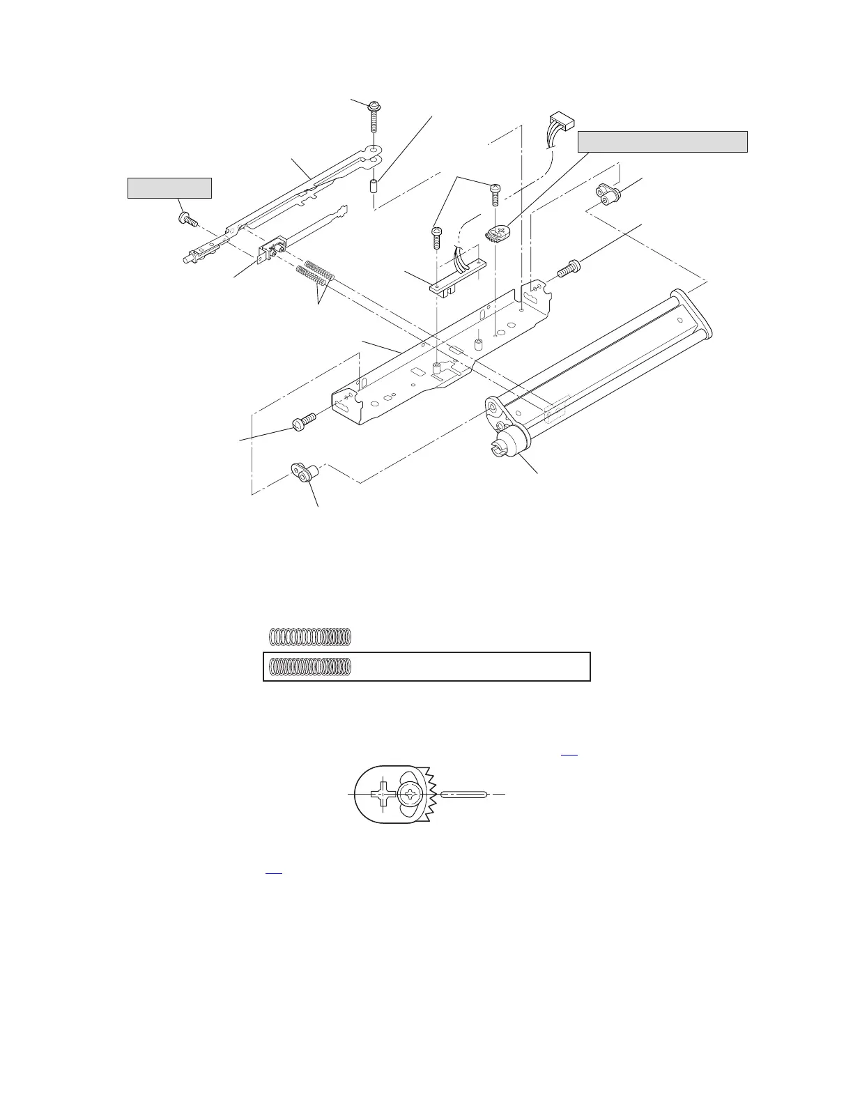
SA, Ribbon Tension Shaft R
NO.0, TFH (BH),
M2x4 (NI)
NO.0, TFH (BH),
M2x4 (NI)
SA, Ribbon Sensor Frame R
Spring R, Ribbon Tension
SA, Ribbon Sub Adjust Lever R
SA, Tension Adjust Lever R
SA, Tension
Sensor
PH (PW), M2x8
NO.0, TFH,
M2x3 (NI)
Bush 2, Ribbon
Guide Roller
Bush 2, Ribbon Guide Roller
Shaft, Tension Adjust
Cam, Tension Base Adjust
PH, M1.7x4
Notes on reassembling:
• Distinguish the Ribbon Tension Spring R (used here) from the Ribbon Tension Spring F (used in
3-5-8 “Ribbon Tension Shaft F SA”). They look like the same, but the number of turns differs.
18 turns (Spring F, Ribbon Tension)
20 turns (Spring R, Ribbon Tension)
• When assembling the Tension Base Adjust Cam, adjust its position as shown in the figure to set
it at the mechanical center. Then, perform adjustment according to 3.6.2-(2-1) “Tension base
adjust cam position adjustment (For service personnel)” on page 3-
47.
• When assembling the tension adjust screw (PH, M1.7x4), perform 3-6-3 “Ribbon Tension
Adjustment” on page 3-
52.