3-5. Disassembly, Reassembly and Lubrication
3-19 CLP-621 & CLP-631
3-5-10. Main PCB Block, Power Supply Unit and Control Panel Unit
1. Remove the Case U Unit. Refer to 3-5-2 “Case U”.
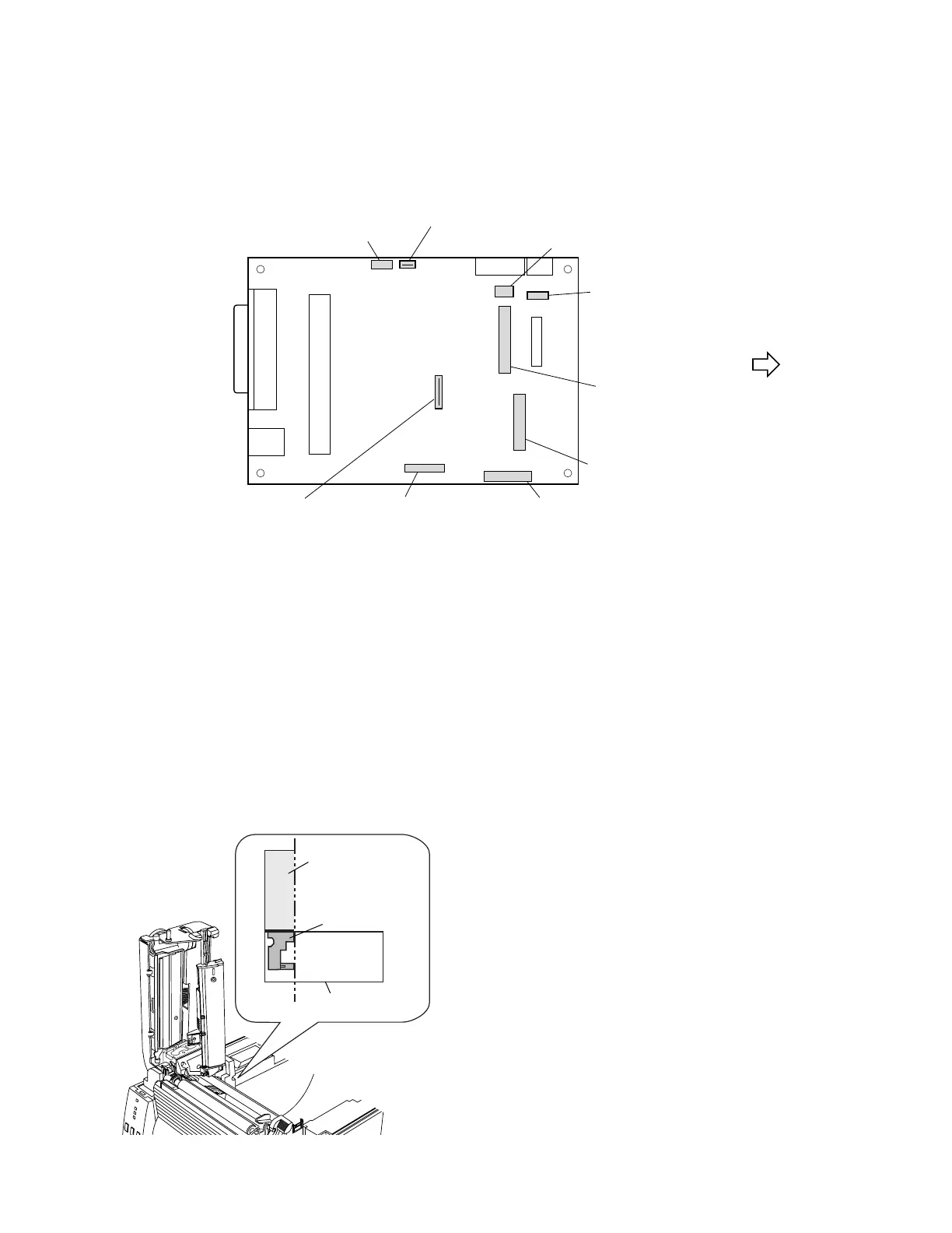
2. Disconnect the following cables from the Main PCB Unit.
• CN4, CN5, CN6, CN7, CN8, CN9, CN10, CN12, CN21
CN6
CN7
CN12
CN9
CN4
CN10
CN21
CN5
CN8
To Transparent Sensor PCB SA
To Reflective Sensor PCB SA
To Head Up Sensor PCB SA
To Motor SA
To Head SA
To Ope-pane PCB SA
To Power Supply Unit
Unit, Main PCB
To Ribbon Main PCB
(on the Ribbon Unit)
To Ribbon Main PCB
(on the Ribbon Unit)
Front
3. Remove 4 screws (PHT (BH2T), M3x8), 1 screw (BH, M4x4 (NI)) and 1 washer (EXT. T, 4 (NI)),
and then detach the Main PCB Block upwardly.
4. Remove 3 screws (PHT (BH2T), M3x8), 1 screw (BH, M4x4 (NI)) and 1 washer (EXT. T, 4 (NI)),
and 1 screw (BH (N), M3x6) and 1 washer (EXT. T, 3 (NI)), disconnect the Power Cable SA,
and detach the Power Supply Unit.
5. Remove the Control Panel Unit upwardly by releasing the hook part.
6. Remove the Ope-pane Cable Cushion and the Ope-pane Cable from the Control Panel Unit.
7. Remove the Core SA which is attached to the Case L.
Main PCB Block
Head Wire Cover
(Media Guide End)
Unit, Mechanism
Align.