ENGLISH
EN
Operator’s Manual - BSW 28 9
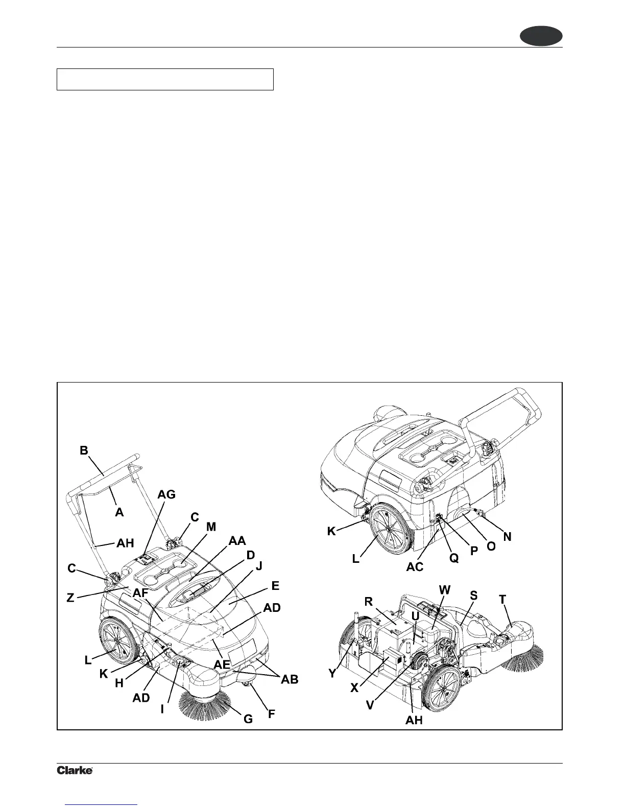
OUTER AND INNER STRUCTURE
(See Fig. 1)
A. Drive control lever
When pulling it gradually towards the handlebar, the
machine starts. Drive speed is increased by pulling the
lever further.
B. Handlebar
C. Handlebar adjusting knobs
D. Filter shaker knob
E. Hopper
F. Front steering wheel
G. Side broom
H. Side broom lifting/lowering lever
I. Side broom height adjusting knob
J. Main broom
K. Main broom height adjusting knobs
L. Rear driving wheels
M. Can holders
N. Battery charger cable
O. Battery charger cable housing
P. Side broom motor circuit breaker
Q. Main motor circuit breaker
MACHINE DESCRIPTION
R. Battery
S. Dust filter
T. Side broom motor
U. Main motor
V. Drive system gear (by clutch)
W. Vacuum fan
X. Battery charger
Y. Vacuum system motor lamellar fuse (7.5 A)
Z. Hood
AA. Hopper upper handle
AB. Hopper lower handles
AC. Serial number plate/technical data/conformity
certification
AD. Side skirts
AE. Front skirt
AF. Rear skirt
AG. Control panel
AH. Drive control lever adjuster
Figure 1
 Loading...