Page -22- Clarke
®
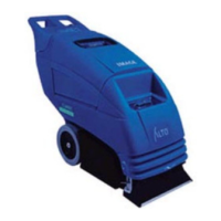
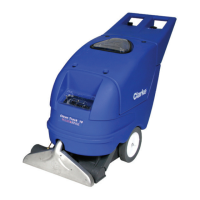
Operator's Manual IMAGE 26B
Clarke
®
Image 26B
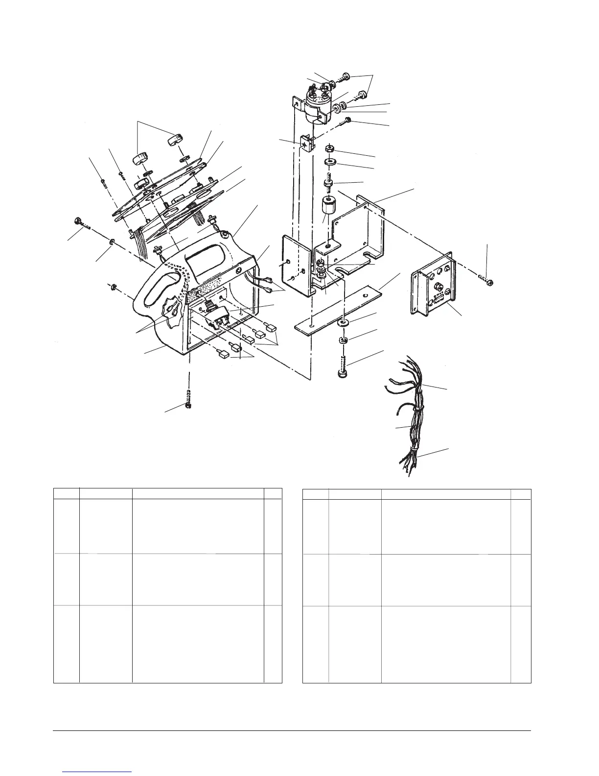
Handle Assembly Drawing and Parts List 8/03
1 34813A Handle 1
2 980645 Washer,
3
/8 Flat 2
3 962522 Screw,
3
/8 -16 x 2 2
4 962968 Screw, 10-24 x ½ 4
5 85313C Screw, 6-32 x
3
/8 4
6 55502A Knob 2
7 77368A Label, Control Panel 1
8 66257A Panel, Control 1
9 44309A Module, Control 1
10 53077B Switch, Forward 2
11 40158A Switch, Reverse 1
12 47380A Switch, Key 1
14 41438B Circuit Breaker, 7A (br. motor) 2
15 41422B Circuit Breaker, 25A (vac/tr mtr) 3
16 41161A Control Motor, Quad 1
17 40190B Harness, Wiring 1
18 962430 Screw, ¼-20 x ½ 3
Ref Part No. Description Qty
1
2
3
4
5
6
7
8
9
10
11
12
14
15
17
18
19
20
21
16
23
24
25
26
27
18
Ref Part No. Description Qty
19 980657 Washer, ¼ Lock 4
20 980646 Washer, ¼ Flat 5
21 64247A Plate, Retaining 1
22 40006A Harness, Wire 1
23 962350 Screw, 10-32 x ½ 5
24 61687A Weldment, Handle Cont 1
25 854849 Insulator 1
26 83302A Stud, ¼-20 1
27 41801A Contactor 36V 1
28 920208 Nut 1
29 47905A Terminal 6
30 40005B Harness, Wire 1
31 912287 Rectifier 1
32 81102A Nut, Nylock 2
33 30033A Gasket, Handle 1
34 30032A Gasket, Control Panel 1
35 Page 23 (see item #35) 2
29
22
30
32
19
20
29
19
19
20
20
23
31
35
33
34
28
19
 Loading...