Home
Clarke
Floor Machine
Image 26B
Clarke Image 26B User Manual
4
of 1
of 1 rating
40 pages
Give review
Manual
Specs
To Next Page
To Next Page
To Previous Page
To Previous Page
Loading...
Page -30-
Clarke
®
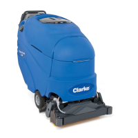
Operator's Manual IMAGE 26B
Clarke
®
Image 26B
Transaxle Parts List 4/03
1
2
3
4
Ref
#
Part No.
Description
Q
ty
1
50983A
52660A
Coupler, Transaxle
1
2
51056A
50252A
Mount, Transaxle
1
3
40628A
50251A
Brush, Carbon
1
4
40627A
50250B
Motor, Transaxle
1
50008C
50
008B
29
31
Table of Contents
Table of Contents
2
Operator Safety Instructions
3
Introduction and Machine Specifications
5
Transporting the Machine
6
Machine Controls
7
How to Prepare the Machine for Operation
10
Machine Operating Instructions
14
Maintenance Instructions
17
How to Correct Problems in the Machine
20
Recovery Tank and Hose Assembly
21
Handle Assembly
22
Rear Panel Assembly
23
Solution Tank Assembly
24
Solution Delivery System
25
Frame Assembly
26
Battery Tray
27
Recovery Tool Assembly
28
Brush Assembly
29
Transaxle Parts List 4/03
30
Vac Motor Assembly
31
Battery Charger (40506A, 40507A, 40505A)
32
Battery Charger (40512B, 40506B)
33
Available Accessories 8/03
34
Wiring Schematic 10/02
35
Connection Diagram 10/02
36
Flow Diagram
37
4
Based on 1 rating
Ask a question
Give review
Questions and Answers:
Need help?
Do you have a question about the Clarke Image 26B and is the answer not in the manual?
Ask a question
Clarke Image 26B Specifications
General
Brand
Clarke
Model
Image 26B
Category
Floor Machine
Language
English
Related product manuals
Clarke IMAGE 16 I
61 pages
Clarke Focus II
139 pages
Clarke FOCUS II MICRO RIDER 26D
135 pages
Clarke TFC 400
12 pages
Clarke MA50 15B
87 pages
Clarke ultra speed
37 pages
Clarke CFP Pro 17HD
12 pages
Clarke CLEAN TRACK 16
81 pages
Clarke Clean Track 12
60 pages
Clarke Ultra Speed Burnisher
37 pages
Clarke Clean Track® L24 56317170
85 pages
ULTRA SPEED BURNISHER 1700
20 pages