Page -8- Clarke
®
Operator's Manual IMAGE 26B
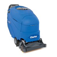
The Brush Adjustment Control Knob (See
figure 4, A)
The brush lift control knob is located at the rear of the
machine. The knob is adjustable for many types of
carpet. This setting need not be adjusted between
uses. The settings are retained.
Brush Pressure Meter
The brush pressure meter indicates the relative
amount of pressure the brush is putting on the floor.
To maximize run time on a battery charge, keep the
light bars towards the center of the green area. To
avoid damage to the brush motors, do not run the
machine in the "red" area.
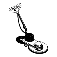
The Recovery Tool Handle (See figure 5, A)
The recovery tool handle is located on the back of
the machine. This handle lowers the recovery tool
and brush.
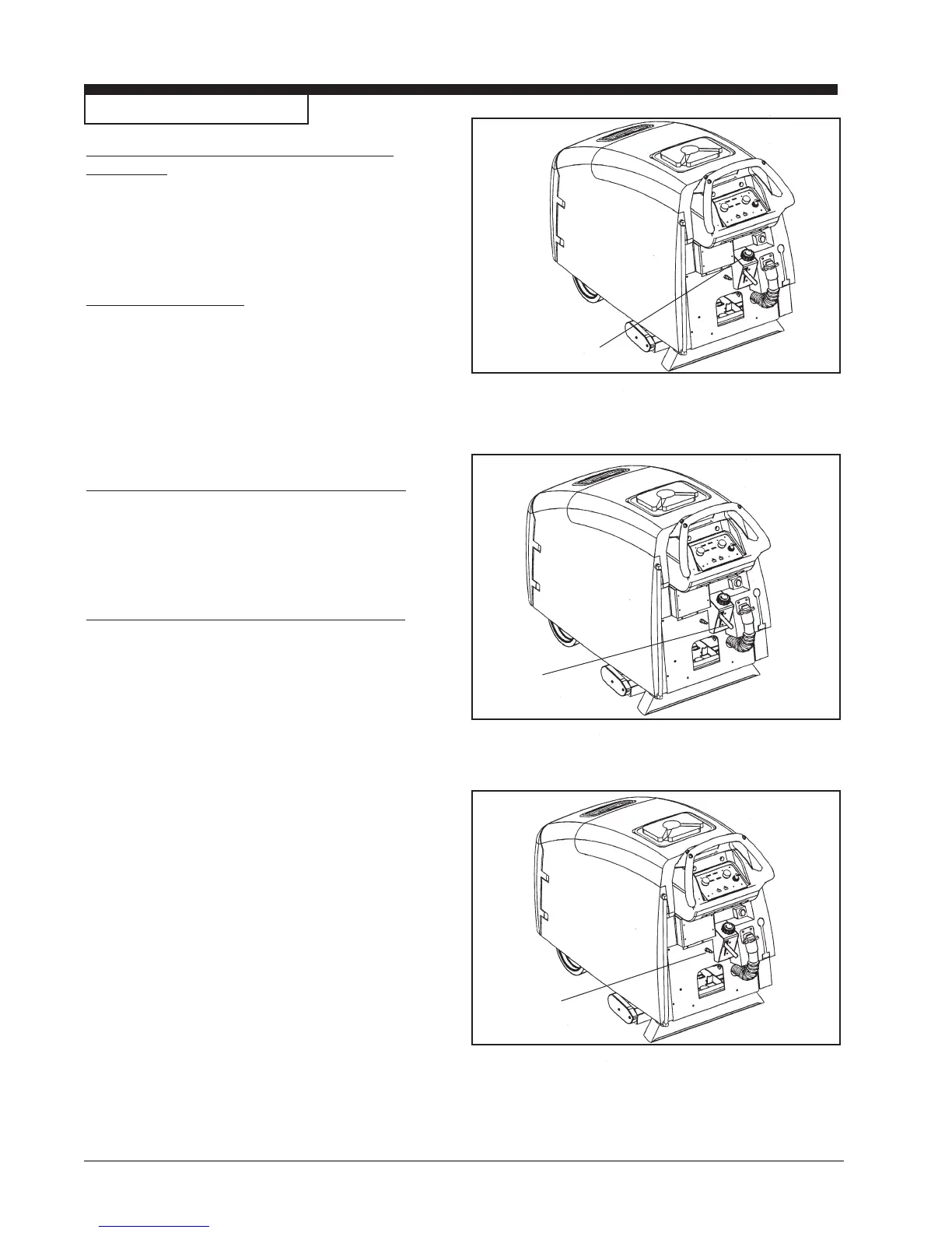
Accessory Hose Connector (See figure 6, A)
The accessory hose connector is used to hook-up
optional auxiliary floor tools and to redirect the
solution flow. Use hose coupler (P.N. 30108A) to
connect accessory hose to recovery shoe hose.
THE CONTROLS (cont.)
Figure 4
Figure 5
Figure 6
A
A
A