750-392
CBEX-DE
1-9
Component Locations
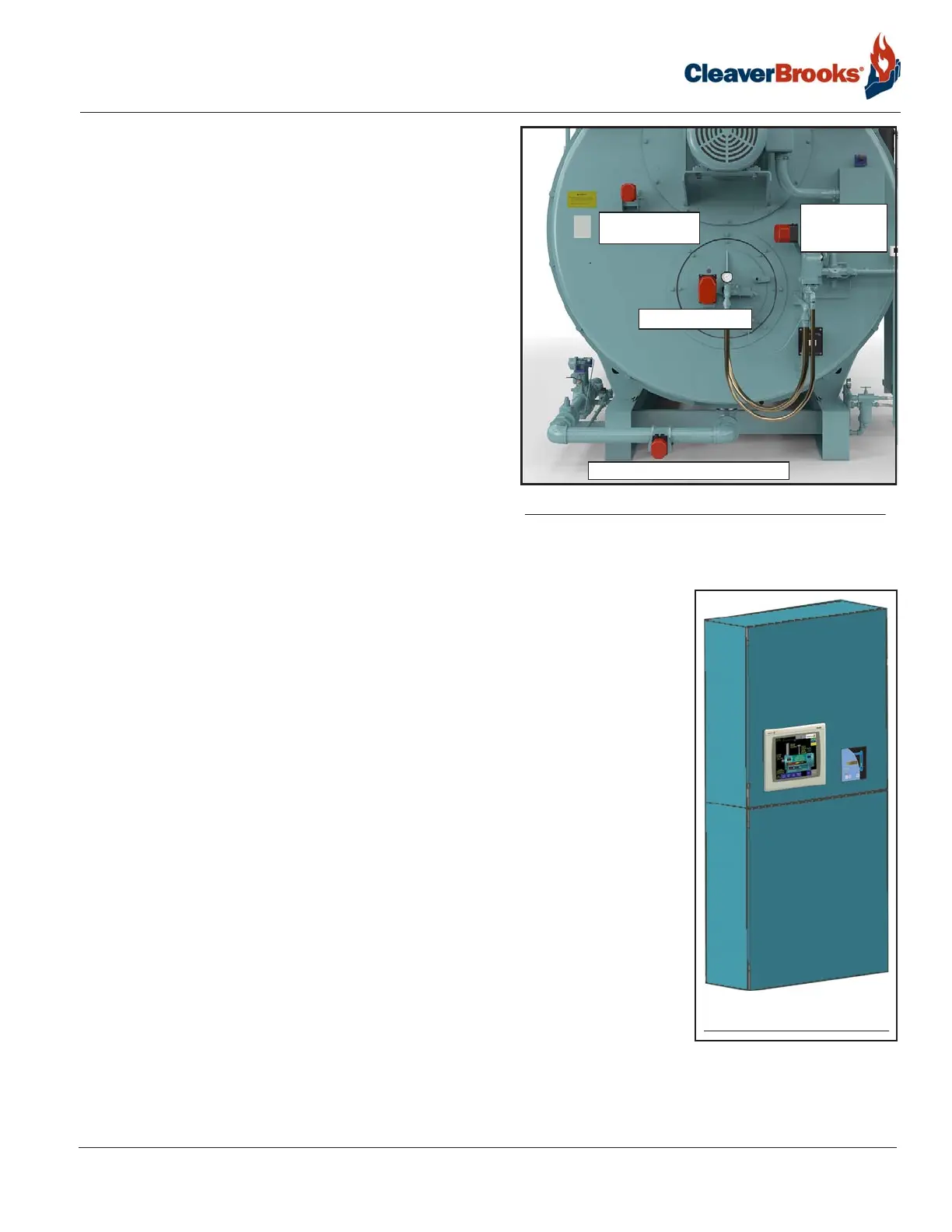
1.2.7 — Actuators
Individual actuators for fuel, air, and FGR are part of the
standard parallel positioning combustion control system,
and are positioned via Modbus signal from the Hawk con-
trol system.
Actuators are connected in series with the air damper actu-
ator last in the sequence. Actuators may use quick discon-
nect cables or may be hard wired depending on the
installation.
For actuator setup and configuration information as well as
combustion setup procedures, see the appropriate Hawk
controls manual.
A single-point positioning linkage system is available for
700/800 HP boilers.
1.2.8 — Control Panel
A common enclosure houses both the control panel and the electrical entrance
panel. The upper and lower sections are divided by a partition with a separate
hinged door for each section.
The upper section (low voltage) houses the boiler control system, including the PLC
and associated modules, the flame safeguard, the Hawk HMI touch screen, and the
LevelMaster panel.
External switches and indicator lights can vary according to options selected. A typ-
ical configuration will include switches for:
• FSG reset
• ALWCO reset
• Burner switch
• Fuel selector switch
The standard control system is the Cleaver-Brooks Hawk 1000, which includes a
4” touch screen.
The optional Hawk 4000 features a 7” touch screen, with a 10” screen optional.
The principal components of the HAWK 1000 are the Programmable Logic Control-
ler (PLC), touch screen Human Machine Interface (HMI), and the Flame Safety
Control. The system also includes 24VDC power supplies and various relays and circuit breakers.
FUEL 1 (GAS BUTTERFLY VALVE)
FUEL 2
(FUEL OIL
CONTROLLER)
FLUE GAS
RECIRCULATION
COMBUSTION AIR
FIGURE 1-11. Actuators
FIGURE 1-12. Control/
entrance panel