Introduction
1-10
750-392
CBEX -DE
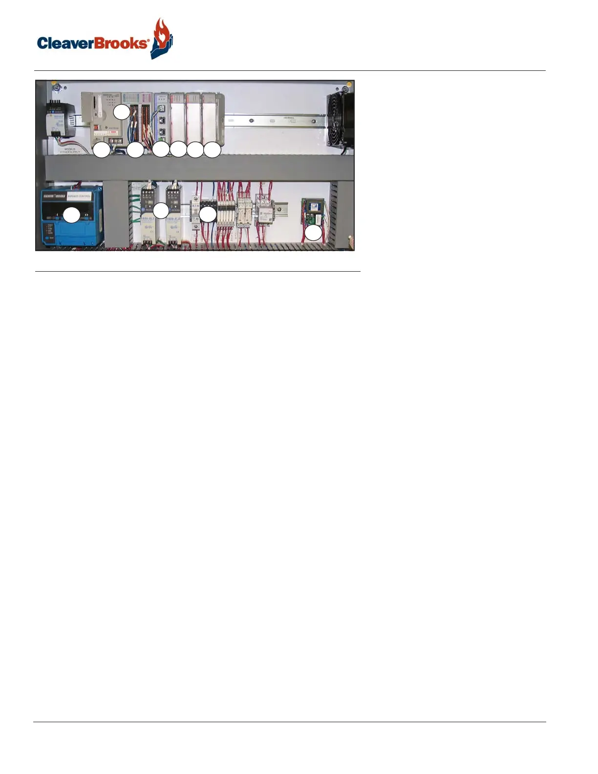
1. Base Unit
1a. L24ER Programmable Logic Controller (PLC)
1b. Embedded I/O
2. SM2 Modbus Communications Module
3. Digital Inputs
4. Digital Outputs
5. Analog Inputs (optional)
6. Burner Control
7. Power supplies
8. Circuit breakers, relays, fuses,
etc.
9. ALWCO control
FIGURE 1-13. Hawk 1000 components, typical
The Base Unit consists of the Processor (CPU) which holds the program logic and configuration for the boiler
controller and embedded I/O modules which consist of discrete inputs, discrete outputs, and analog inputs. The
program logic is password-secured at the factory.
The SM2 module handles the Modbus communications between the PLC and other devices.
The Module Power Supply powers the Base Unit and the I/O modules. The remainder of the PLC rack is for the
discrete input and output modules, and for analog input module (optional).
I/O modules are used to send and receive control and communication signals to/from other parts of the system.
A Right End Cap Terminator is required to complete the modular communication bus. It attaches to the right side
of the last module in the rack.
An optional analog input module can be added to the PLC to provide additional functionality.
The HMI displays numerous boiler parameters at a glance and provides easy menu navigation for configuring
system parameters, setting of combustion, monitoring the boiler processes, and managing and annunciating sys-
tem alarms.
The HMI communicates with the PLC via Ethernet and is
powered
by a 24
VDC
din-rail mounted power
suppl
y
.
NOTE: For complete information on the boiler control system consult the Hawk manual, provided separately.
1b
2
3
5
6
8
6
1
1a
7
9
4