CLIMATEMASTER WATER-SOURCE HEAT PUMPS
Tranquility
®
Water-to-Water (TMW) Series
Rev.: 04/15/16
14
ClimateMaster Water-Source Heat Pumps
Ground-Loop Heat Pump Applications
Pre-Installation -
Prior to installation, locate and mark all
existing underground utilities, piping, etc. Install loops
for new construction before sidewalks, patios, driveways,
and other construction has begun. During construction,
accurately mark all ground loop piping on the plot plan
as an aid in avoiding potential future damage to the
installation.
Piping Installation -
All earth loop piping materials should
be limited to only polyethylene fusion for inground sections
of the loop. Galvanized or steel fi tting should not be used
at any time due to their tendency to corrode. All plastic
to metal threaded fi ttings should be avoided due to their
potential to leak in earth coupled applications and a fl anged
fi tting substituted. P/T plugs should be used so that fl ow
can be measured using the pressure drop of the unit heat
exchanger in lieu of other fl ow measurement means. Earth
loop temperatures can range between 25 to 110°F [-4 to
43°C], and 2.25 to 3 gpm of fl ow per ton [2.9 l/m to 3.9
l/m per kW] of cooling capacity is recommended in these
applications. Upon completion of the ground loop piping,
pressure test the loop to assure a leak free system. Horizontal
Systems: Test individual loops as installed. Test entire
system when all loops are assembled. Vertical U-Bends and
Pond Loop Systems: Test Vertical U-bends and pond loop
assemblies prior to installation with a test pressure of at least
100 psi [689 kPa].
Flushing the Earth Loop -
Upon completion of system
installation and testing, fl ush the system to remove all
foreign objects and purge to remove all air. Flush the loop
fi rst with the unit isolated to avoid fl ushing debris from the
loop into the unit heat exchanger.
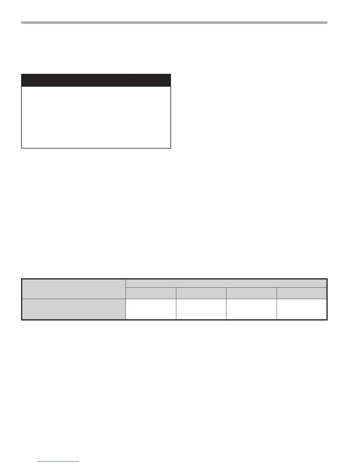
Table 2: Antifreeze Percentages by Volume
Antifreeze -
In areas where minimum entering loop
temperatures drop below 40°F [5°C] or where piping will
be routed through areas subject to freezing, anti-freeze
is needed. Alcohols and glycols are commonly used as
antifreezes, however your local sales manager should
be consulted for the antifreeze best suited to your area.
Low temperature protection should be maintained to
15°F [9°C] below the lowest expected entering loop
temperature. For example, if 30°F [-1°C] is the minimum
expected entering loop temperature, the leaving loop
temperature would be 25 to 22°F [-4 to -6°C] and low
temperature protection should be at 15°F [-10°C] e.g.
30°F - 15°F = 15°F [-1°C - 9°C = -10°C]. All alcohols should
be premixed and pumped from a res er voir outside of the
building when possible or introduced under water level to
prevent fuming. Initially calculate the total volume of fl uid
in the piping system. Then use the percentage by volume
shown in Table 2 for the amount of an ti freeze. Antifreeze
concentration should be checked from a well mixed
sample using a hydrometer to measure specifi c gravity.
Low Water Temperature Cut-Out Setting -
CXM or DXM Control:
When an an ti freeze is se lect ed, the LT1 jumper [JW3]
should be clipped to select the low tem per a ture
(An ti freeze 15°F [-9.4°C]) setpoint to avoid nuisance
faults. See Figure 4.
CAUTION!
CAUTION!
The following instructions represent industry
accepted installation practices for Closed Loop Earth
Coupled Heat Pump Systems. They are provided to assist
the contractor in installing trouble free ground loops. These
instructions are recommendations only. State and Local
Codes MUST be followed and installation MUST conform to
ALL applicable Codes. It is the responsibility of the Installing
contractor to determine and comply with ALL applicable
Codes and Regulations.
Type
Minimum Temperature for Low Temperature Protection
10°F [-12.2°C] 15°F [-9.4°C] 20°F [-6.7°C] 25°F [-3.9°C]
Methanol
100% USP food grade Propylene Glycol
Ethanol*
25%
38%
29%
21%
25%
25%
16%
22%
20%
10%
15%
14%
* Must not be denatured with any petroleum based product
 Loading...


