THE SMART SOLUTION FOR ENERGY EFFICIENCY
Tranquility
®
Water-to-Water (TMW) Series
Rev.: 04/15/16
17
climatemaster.com
WARNING!
CXM/DXM, LONWORKS, OR MPC CONTROL OPERATION
Note: See CXM AOM (part #97B0003N12), DXM AOM (part #97B0003N13), Lon Controller AOM (part
#97B0013N01) or MPC Controller AOM (part #97B0031N01) on the web at climatemaster.com
ALL wiring diagrams are available at climatemaster.com
Figure 5: Field Wiring of 24 Volt Motorized Valve for Units Size 120-340
Electrical - Accessories
Coil
VR 1
6
8
Refrigerant
HP Switch
Circuit #1
VR3
NO
RED
RED
Coil
Valve
Relay 3
Water
High Pressure
Switch NC
Notes - Disconnect red wire at refrigerant HP switch connect to N.O. contact,
connect new red wire from N.O. contact to refrigerant HP switch.
Valve Relay 1, 2 - 13B0001N01 (SPDT) VR1, VR2
Valve Relay 3 - 13B0004N01 (DPDT) VR3
Coil
6
8
Refrigerant
HP Switch
Circuit #1
VR3
NO
RED
RED
Coil
Valve
Relay 3
Water
High Pressure
Switch NC
Coil
VR2
2
4
Refrigerant
HP Switch
Circuit #2
VR3
NO
RED
RED
,
2
4
Refrigerant
HP Switch
Circuit #2
VR3
NO
RED
RED
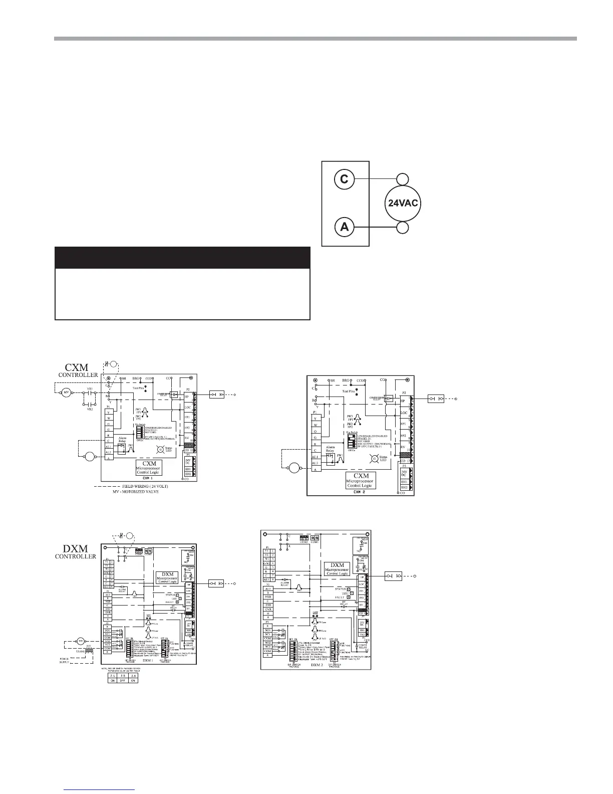
WARNING! Never jumper terminal “A” from CXM or DXM
board #1 to CXM or DXM board #2 on multi-compressor/
control bound units. See Figure 5 in electrical section of this
document for motorized valve wiring.
Accessory Connections - A terminal paralleling the
compressor contactor coil has been provided on the
CXM/DXM control of the TMW line. "A" has been
provided to control accessory devices, such as water
valves, electronic air cleaners, humidifi ers, etc. Note:
This terminal must be used only with 24 Volt signals
and not line voltage signals. This signal operates with
the compressor contactor. See Figure 8 or the wiring
schematic for details.
24 Volt Accessory Wiring
These terminals may be used to
power 24 volt water valves on
units size 036, 060
CXM/DXM Terminal Strip
 Loading...


