OPERATING MANUAL
800.749.2761 www.coachcomm.com
17
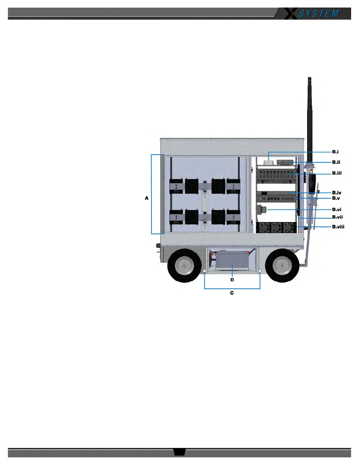
Rear View
A. RT Storage - Houses RT brackets (See page 64 for more information.)
B. Rear Rack - 23RU shock-mounted, LED-lit rack area that contains the following:
i. Inverter ComBox - Provides
status information for AC
Inverter to the PC (See page
29 for more information.)
ii. PC - Provides interface with
X-Ware (Intel
®
Core™ i3
processor, 4GB RAM, 256GB
hard drive, and Windows
®
7
operating system)
iii. Wired Assignment Module
(WAM) (See page 26 for
more information.)
iv. Drive System Switch -
Provides power to the drive
system (See page 20 for
more information.)
v. Rear Patch Panel - Contains
Main Power Switch, Alarm
Switch, RT connections,
and dry pair connections
(See page 30 for more
information.)
vi. Inverter Outlet - Inverter
power for Rack Power
Distribution Unit. Rack
components powered by
inverter in case of AC power
loss.
vii. AC “Rack” Power Strip - Supplies power to rack components (See page 29 for more information.)
viii. Fans - Circulate air to 5-Bay Battery Chargers
C. Stabilizing Slots - Insertion points for cart stabilizers
D. Power Bay Access - Houses the cart’s AC Inverter and Battery Bank system (See page 27 for more
information.)
Figure 17: Sideline Cart Front View