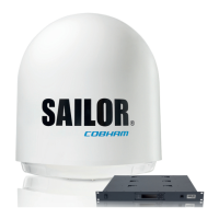
SAILOR XTR Ka system
98-175666-A Chapter 1: Introduction 1-8
The BDU has a an On/Off power switch and a LAN connector at the front for accessing the
service port. The unit is AC powered.
1.1.3 GX Modem Unit (modem)
The modem (GMU) comes in a 19” rack version. The modem has the following interfaces
and switch:
• 8 + 2 ports, one active for modem control and user equipment.
• 3 x F connectors for Rx and Tx cables (75 Ohm) to ACU (Rx2 not active).
• RS-422 interface for modem control.
• 2 x RS-232 interfaces, one for modem control, one not active.
BDU connector ID Type Function
NMEA0183 RJ-45 Vessel gyro input
GPIO RJ-45 General Purpose I/O
LAN 1 RJ-45 VSAT modem
LAN 2 RJ-45 User LAN
LAN 3 RJ-45 User LAN
LAN 4 RJ-45 User LAN
RS 232 RJ-45 VSAT modem serial interface
RS422 RJ-45 VSAT modem serial interface
TX In F VSAT modem TX (75 Ohm)
RX Out F VSAT modem RX (75 Ohm)
Antenna N ADU signal and power (50 Ohm)
LAN RJ45 Front LAN service port (LAN 5)
Table 1-1: BDU connectors
Figure 1-8: BDU front panel
465
31.75
482.6
On/Off switch
Service port
Figure 1-9: GMU (connector panel)
Á£ÃÁ¯ °µ ²»½
°·Þ
²¸¡
²±×ÐÒÒ²±×ÒÑÒ ÃÁ´
GMU
 Loading...

