98-175666-A 3-1
Chapter 3
Interfaces 3
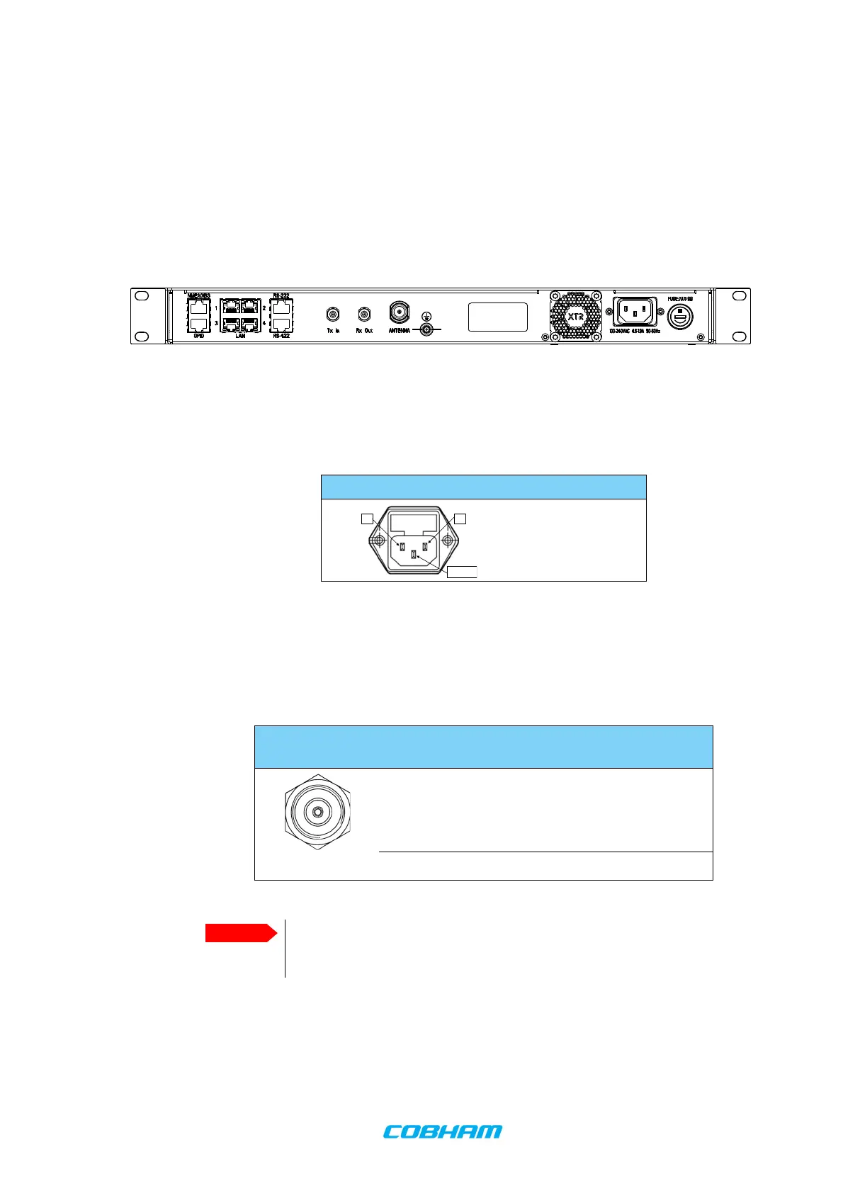
3.1 Connector panel of the BDU
3.1.1 AC input connector
Connect the power cable to the AC power connector.
3.1.2 ADU connector
There is just one cable from the BDU to the ADU. This is used to power the ADU, supply
10 MHz clock, handle all communication between BDU and ADU, and deliver the VSAT Rx
and Tx signals.
Figure 3-1: BDU: connector panel
Outline (on the BDU) Voltage range
100–240 VAC
Table 3-1: AC power connector
Outline
(on the BDU)
Conductor Pin function
Inner DC to ADU
10 MHz clock to ADU
BDU to ADU internal communication
VSAT Rx/Tx
Outer GND (Shield)
Table 3-2: N connector, outline and pin assignment
Do not use TNC connectors on the ADU antenna cable or
on pigtails. TNC connectors cannot carry the DC current
for operating the ADU.