EasyManuals Logo

COBHAM SAILOR 6000 User Manual

COBHAM SAILOR 6000
40 pages
To Next Page IconTo Next Page
To Previous Page IconTo Previous Page
Page #25 background imageLoading...
Page #25 background image
Chapter 2: Electrical Installation 3-5
Electrical installation
98-131571-B
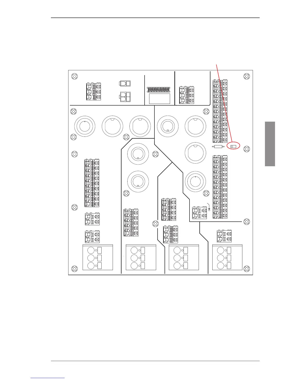
3.6 MF/HF CAN-bus termination
The jumper W1 terminates the MF/HF CAN-bus. If an external CU is connected to the console connection
board and the cable is more than 6 m long, remove the jumper W1. The termination must then be connected
to the CU at the most distant point from the transceiver.
99-130999
J42
1
J41
1
J30
1
J61
J52
J43
J26
J25
J24
J60
J36
J21
J10
J51
J70
J50
J40
J32
J35
J80
J33
1
J31
1
J22
1
J23
1
W1
R1
J11
J12
J34
J20
LABEL
Terminal
mini-C
3
Power IN 24VDC
Power IN 15VDC
Power IN 24VDC
Power IN 24VDC
GND
GND
GND
GND
Out
3
3
3
MSG
TEST
1
2
1
2
1
2
2
1
1 SHLD
2 GND
3 +24V
4 +15V
5 CAN H
6 CAN L
8 CU_ON
7 C_GND
9 RX+
11 TX+
10 RX-
12 TX-
Thrane & Thrane 38-130999-F
Console 6000 Connection
GND
NC
NC
24VDC-
24VDC+
4
3
2
1
3 GND
1 24VDC+
2 24VDC-
5 CAN_L
3C_GND
4 CAN_H
2 15VDC+
1 SHLD
MSG Terminal
3 GND
2 24VDC-
1 24VDC+
2 AIS-
1 AIS+
7 Ext.Sp+
Forced
9 Lo Pwr
8 Ext.Sp-
6 GND
5 DSC Al
4 DSC OC
3 AUX OC
2 VDR-
1 VDR+
ACC
+
-
+
-
+
-
+
-
Power Out
AIS
AUX
12 TX-
11 TX+
10 RX-
9 RX+
8 CU_ON
7 C_GND
6 CAN L
5 CAN H
4 +15V
3 +24V
2 GND
1 SHLD
1 24VDC+
2 24VDC-
2 24VDC-
1 24VDC+
Power
MF/HF
Ext. CU
Telex
Handset
TU-CU Bus
3 GND
LIGHT
2 NMEA-
1 NMEA+
TU
Select
Printer PWR
Power IN 24VDC
Dimmer
Gooseneck
MF/HF
VHF &
0183
NMEA
2182
Power
Terminal
Antenna
TCU
PRINTER
TERMINAL/
MESSAGE
AUX
Handset
ACC
VHF
ETHERNET
MF/HF CAN-bus termination
W1

Questions and Answers:

Question and Answer IconNeed help?

Do you have a question about the COBHAM SAILOR 6000 and is the answer not in the manual?

COBHAM SAILOR 6000 Specifications

General IconGeneral
BrandCOBHAM
ModelSAILOR 6000
CategoryMarine Equipment
LanguageEnglish

Related product manuals