4-1
Installation cables
Chapter 4: Installation cables
98-131571-B
Chapter 4
4 Installation cables
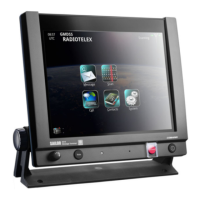
4.1 Console wiring system
The internal wiring of the console has been grouped and numbered in the following drawings, so that each
cableiseasilyidentiedbyitsuniqueidentier.
Numbering
The numbering is grouped in three digits, as indicated below. The type of signal carried is also indicated in the
table listing the internal cables.
X.Y.ZZ
C7=Primaryinternal 1=RF/Antenna X.2.00through19=Control/Data
C8=Duplication,backup,internal 2=Signals X.2.20through29=Relayoutput
C9=Commoninternal 3=DCpower X.2.30through39=Ext.signal
4=ACpower X.3.00through09=HeavydutyDC
(distribution)
X.3.10through19=Singlepower