98-131571-B iii
Chapter 1 General information
1.1 Introduction ......................................................................................................................................1-1
Chapter 2 Installation
2.1 Dimensions ........................................................................................................................................ 2-1
2.2 Drilling and cutting template ....................................................................................................2-3
2.2.2 Tabletop mounting for 3 x 400mm section...............................................................2-4
2.2.3 Bulkheadmountingfor2x400mmsection .............................................................. 2-4
2.2.4 Bulkheadmountingfor3x400mmsection .............................................................. 2-5
2.2.5 Earth stubs mounting ...........................................................................................................2-5
2.2.6 Placement of connection boards and moxa switches .......................................... 2-6
2.3 Mountingtheconsoleontothebulkhead .......................................................................... 2-6
2.4 Paper roll .............................................................................................................................................2-9
2.5 Control units .....................................................................................................................................2-9
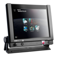
2.6 Message Terminal ........................................................................................................................... 2-10
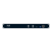
2.7 Power Converter .............................................................................................................................2-10
2.8 Factorycongurationoftheconsole ...................................................................................2-11
Chapter 3 Electrical installation
3.1 Grounding cables ............................................................................................................................ 3-1
3.2 Console light .....................................................................................................................................3-2
3.3 Console Connection Box ............................................................................................................ 3-2
3.4 Connection board ..........................................................................................................................3-3
3.5 Schematic connection board ...................................................................................................3-4
3.6 MF/HF CAN-bus termination ....................................................................................................3-4
3.7 mini-C CAN-bus termination ....................................................................................................3-5
Chapter 4 Installation cables
4.1 Console wiring system .................................................................................................................4-1
4.2 Internal cable overview ...............................................................................................................4-2
4.2.1 Internal cables 4 section console w/2 x MF/HF Radiotelex and mini-C ......4-3
4.2.2
Internal cables 3 section console w/ MF/HF Radiotelex, mini-C and VHF
........ 4-4
Table of Contents