Technical Manual CODEL
9
Installation
Be sure to observe all necessary safety precautions at all times during installation.
All cable gland entry holes are drilled and tapped M20 x 1.5 and are fitted with blanking
plugs.
Cable glands are to be supplied by the customer according to the cables used during
installation.
Mounting Details
After unpacking the equipment check, using the packing list provided, that all items are present. The
Air Quality Monitor (AQM) is carried on a fabricated mounting bracket (if supplied
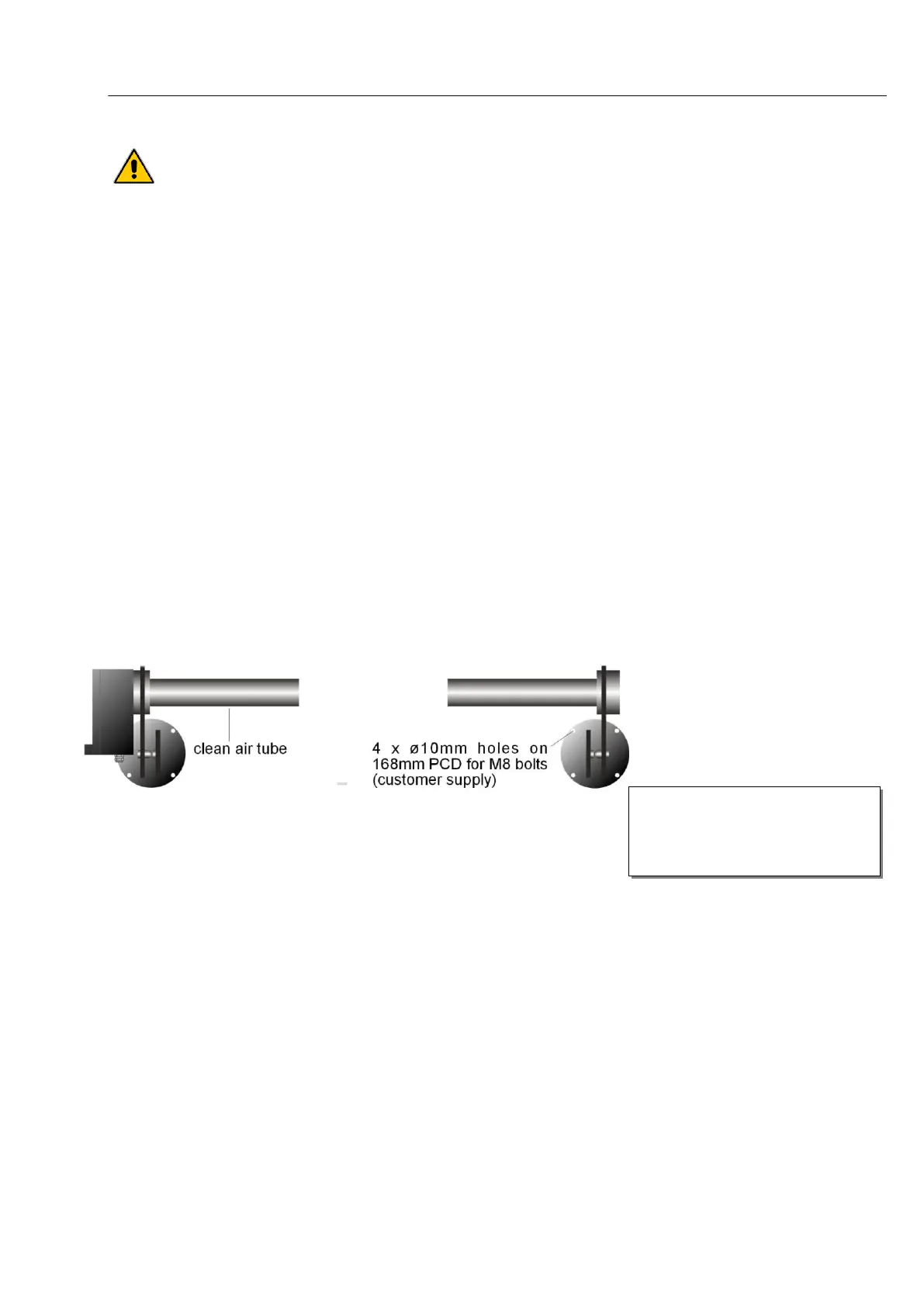
Air Quality Monitor (AQM)
The AQM comprises a transceiver and reflector unit. Secure the AQM to the tunnel wall by the
mounting brackets supplied using 4 x M8 bolts (by others) such that the transceiver and reflector are
approximately 3m apart. The transceiver and reflector should be mounted horizontally and arranged
as illustrated in
Figure .
Figure 5 : AQM – mounting holes
Power Supply Unit (PSU)
Mount the PSU to the tunnel wall again using 4 x M6 bolts (by others). Mounting hole details are
shown in the illustration Figure .
Clean air tubes are supplied and
should be bolted onto the
mounting brackets using the 3 x
M6 bolts provided.