InteliLite Global Guide
24
It is necessary to ensure that potential difference between generator current COM terminal and battery “- ”
terminal is maximally ± 2 V. Therefore is strongly recommended to interconnect these two terminals together.
Note: The controller should be grounded properly in order to protect against lighting strikes. The maximum
allowable current through the controller’s negative terminal is 4 A (this is dependent on binary output load).
For the connections with 12 VDC power supply, the controller includes internal capacitors that allow the
controller to continue operation during cranking if the battery voltage dip occurs. If the voltage before dip is 10 V,
after 100 ms the voltage recovers to 7 V, the controller continues operating. During this voltage dip the controller
screen backlight can turn off and on but the controller keeps operating. It is possible to further support the
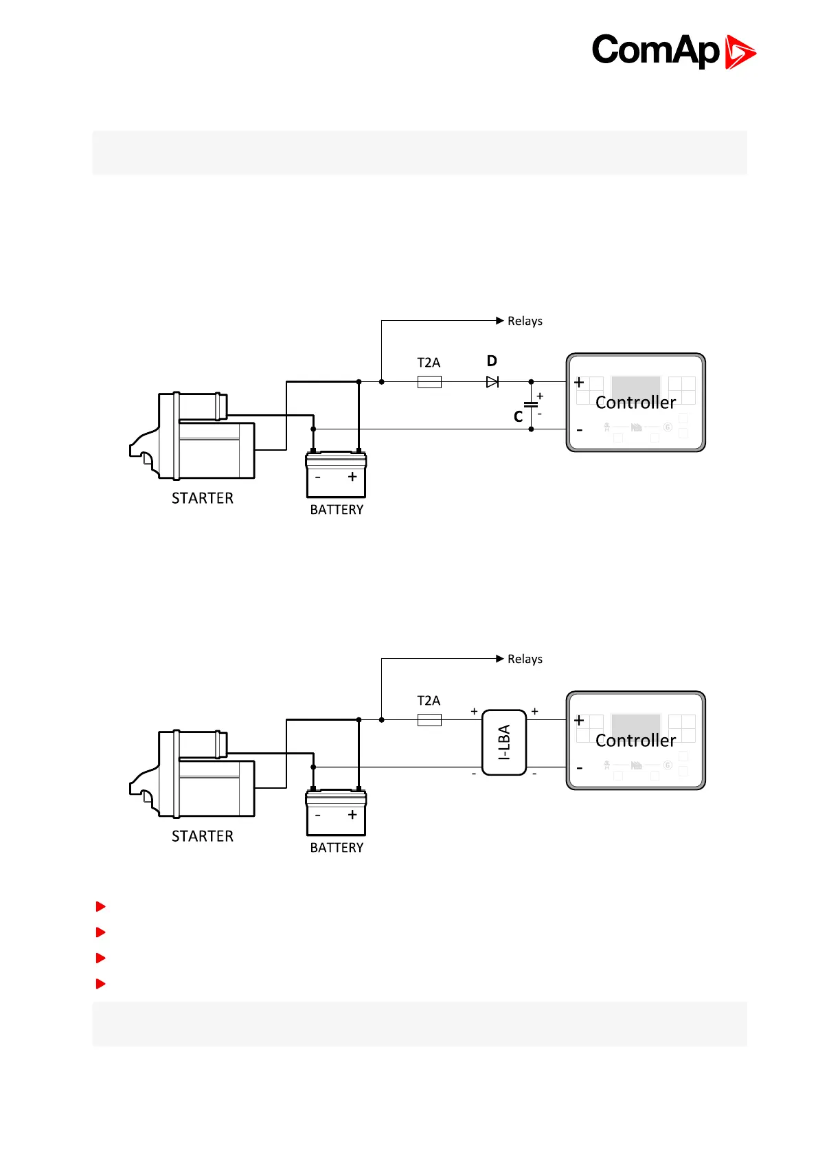
controller by connecting the external capacitor and separating diode or I-LBA module:
The capacitor size depends on required time. It shall be approximately thousands of μF. The capacitor size
should be 5 000 μF to withstand 150 ms voltage dip under following conditions:
Voltage before dip is 12 V, after 150 ms the voltage recovers to min. allowed voltage, i.e. 8 V.
Or by connecting special I-LBA Low Battery Adapter module:
The I-LBA module ensures min. 350 ms voltage dip under following conditions:
RS232 and other plug-in module is connected.
Voltage before dip is 12 V and after 350 ms the voltage recovers to min. allowed voltage 5 V.
The I-LBA enables controller operation from 5 VDC (for 10 to 30 sec).
The wiring resistance from battery should be up to 0,1 Ohm for I-LBA proper function.
Note: I-LBA may not eliminate voltage drop when used with low temperature (-40 °C) version of controller and
display heating element is on (below 5 °C). Current drain of heating element exhausts LBA capacitors very fast.