InteliLite Global Guide
35
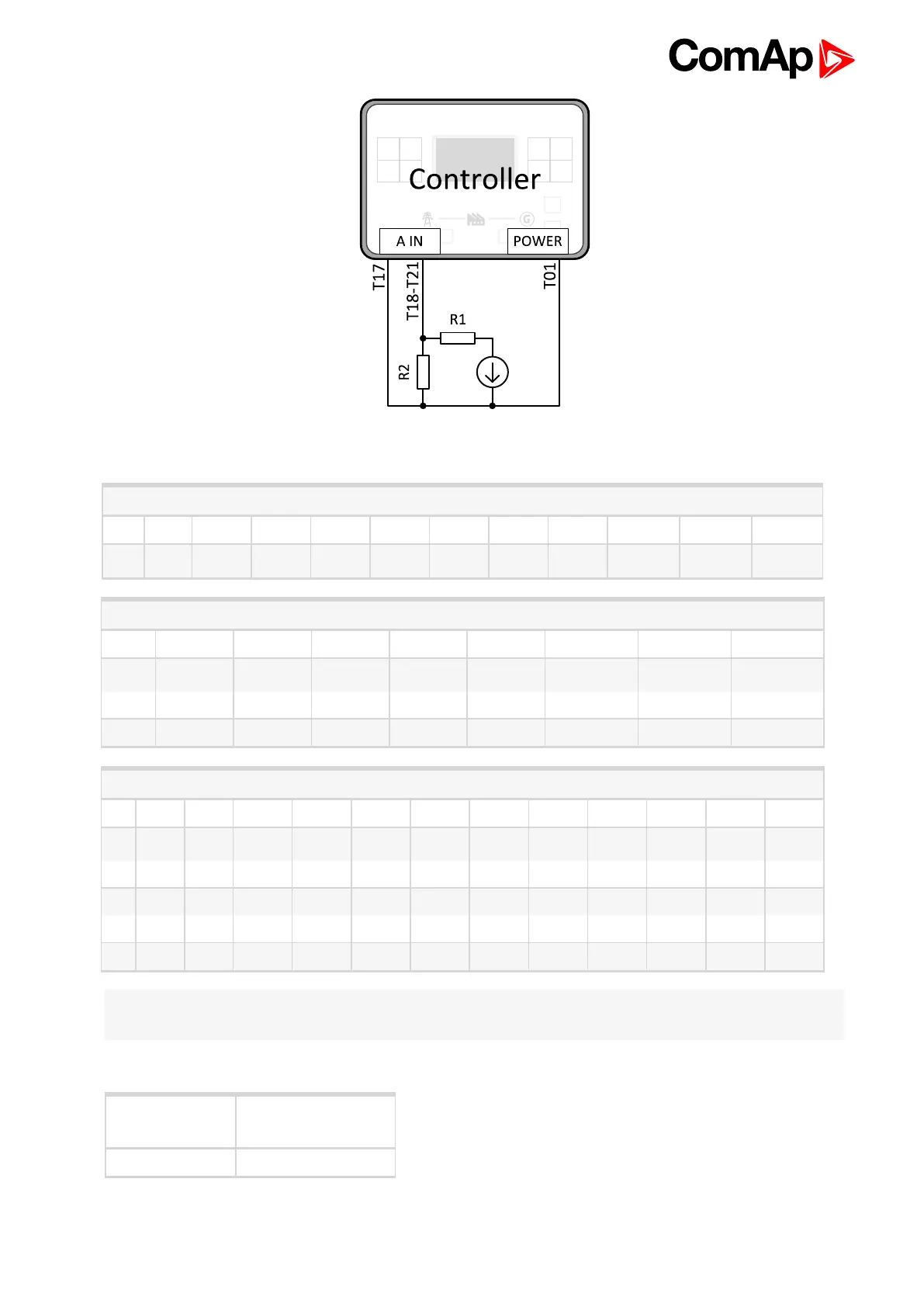
Image 4.12 Wiring of analog input with voltage sensor
0 - 10 V
V 0 1 2 3 4 5 6 7 8 9 10
Ω 81 145 219 306 409 539 685 887 1125 1458 1933
0 - 30 V
V 0 2 4 6 8 10 12 14
Ω 95 134 177 223 274 330 395 465
V 16 18 20 22 24 26 28 30
Ω 543 633 735 853 993 1154 1350 1589
0 - 70 V
V 0 2 4 6 8 10 12 14 16 18 20 22
Ω 99 117 137 155 175 196 219 242 266 291 318 346
V 24 26 28 30 32 34 36 38 40 42 44 46
Ω 375 406 439 473 510 549 589 633 679 729 781 838
V 48 50 52 54 56 58 60 62 64 66 68 70
Ω 873 963 1033 1110 1193 1283 1383 1492 1612 1748 1896 2065
Note: This is a conversion of voltage from voltage sensor to appropriate resistance value. Use resistance
values in LiteEdit2015 to create your specific curve. These values should be used in "Ohm" column.
Current sensors
Sensor’s output
range (mA)
R (Ω)
0-20 100