InteliLite Global Guide
618
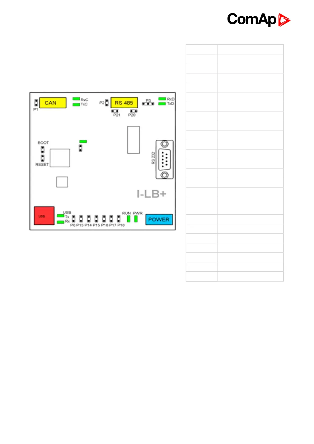
Terminals
POWER Power supply
CAN CAN 1 line
USB USB line
RS232 RS485 line
J13 - J18 SW / HW control
BOOT Programming
RESET Programming / reset
P1 Terminating resistor
P2 Terminating resistor
P3 RS485 or RS232
P8 USB enable/disable
P13 Communication speed
P14 Communication speed
P15 Modem control (HW / SW)
P16 Protocol (Modbus/ComAp)
P17 CAN address
P18
Connection
(direct/modem)
P20 Bias - A
P21 Bias - B
RxC,TxC CAN data
RxD, TxD RSxxx data
Tx,Rx USB USB data
RUN Power
PWR Module state
CAN1 termination (P1)
I-LB+ has included CAN terminating resistor (120 ohm). Close jumper P1 to connect terminating resistor to
CAN bus, open jumper P1 to disconnect terminating resistor.
RS232 or RS485 termination (P2)
I-LB+ has included RS232/RS485 terminating resistor (120 ohm). Close jumper P2 to connect terminating
resistor to RS232/RS485 bus, open jumper P2 to disconnect terminating resistor.
Select RS mode (P3)
Jumper P3 selecting RS mode. When jumper P3 is connected to 1-2(from left side), RS485 mode is activated.
When jumper P3 is connected to 2-3, RS232 mode is actives.
ComAp / Modbus (P16)
Jumper P16 selects between ComAp PC tools and third party PC SW for monitoring with Modbus interface.
ComAp PC tools are selected when P16 is opened; Modbus is selected when P16 is closed.