How to move the robot when the control unit is damaged
41
HS-RC-C5E-MAN_08.fm
00/0511
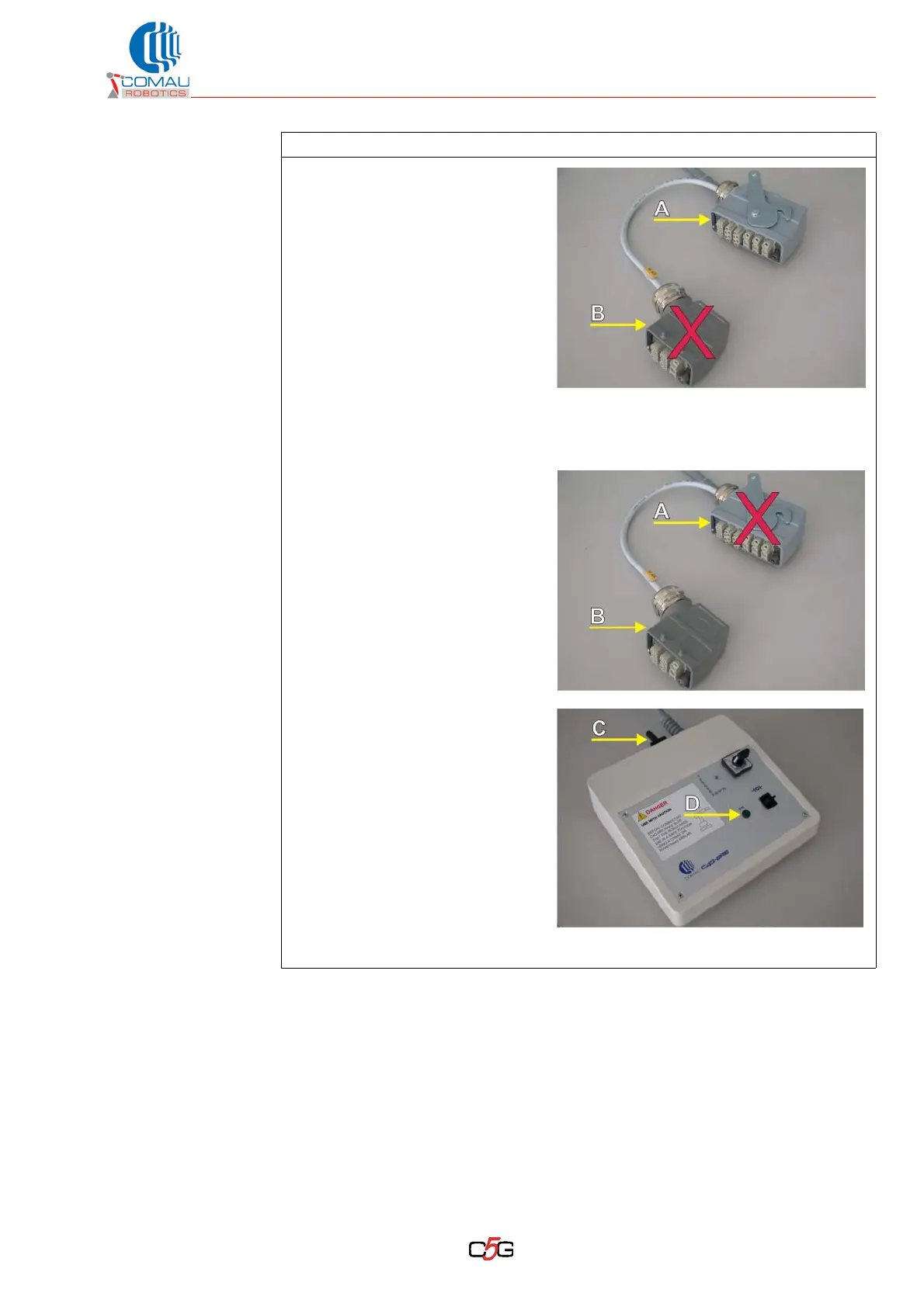
• Connect the movable
connector (A) to the
connector X2 by the Robot
base. The movable
connector (B) is not to be
used and can be left on the
floor.
c. To release axes from 7 to 10:
• Disconnect the power connector from the involved axis. The connector
position is different depending on the installation type.
• Connect the movable
connector (B) to the
connector of the
corresponding axis to be
released. The movable
connector (A) is not to be
used and can be left on the
floor.
d. Supply input power (C) to the
releasing module.
e. The powering is signalled
through the green LED (D)
lighting up.
Illustrative picture
Operating procedure (Continued)