Manutenzione straordinaria - AMS-IAM
72
HS-RC-C5E-AM-IAM_01.fm
00/0211
8.7 AMS-IAM: module replacement
Inverter Axis Module
Front view
Status: – Main switch open (OFF)
Material: – Modul AMS-IAMI
(see Tab. 9.3 - CPU, power supplies
and power modules a pag. 93)
Equipment: – Blade-headed flat screwdriver, short
(4 x 25)
– Blade-headed screwdriver (3 x 15 and
6 x 15)
– T-shaped 5-mm Allen wrench, length
250 mm
– Antistatic arm band
Preliminary procedures / notes
– The antistatic arm band can be connected on one of the pins available inside the
galvanized connector panel (CIP). The connection efficiency is guaranteed only
if the Control Unit is earthed.
– The antistatic band shall be worn during the transducer modules mounting and
dismounting procedure. During the other activities the arm band is not required.
– The images and explanations in the procedure refer to a AMS-IAM double
module. In case of single module, the no. of connectors and fastening screws is
to halved.
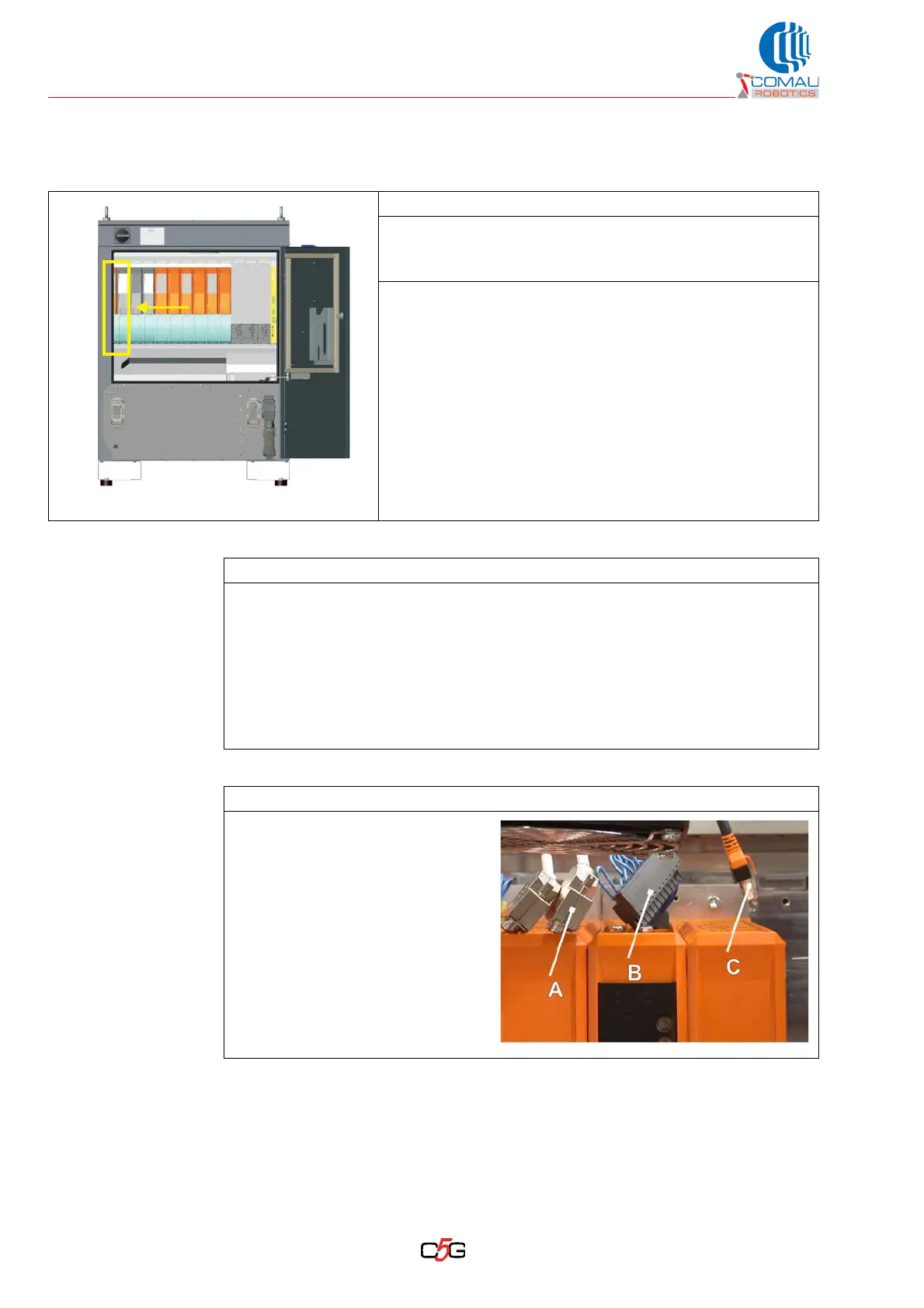
Operating procedure
a. Disconnect the connectors on
the module upper side.
Depending on the connector
type, it may be necessary:
–(A): to unscrew the screws
before removing the connector
–(B): to carry out a direct removal
(connector without fastening
systems)
–(C): to press the tongue and
keep it pressed during the
removal