77
HS-RC-C5E-AM-IAM_01.fm
00/0211
t. Place back all connectors (C), making sure the fitting is followed by a sharp “click”
indicating the fitting has been completely accomplished.
u. Place back the connectors (B).
v. Place the connectors (A) back and the corresponding screws (tighten the screws
without overdoing).
w. Place the terminal back and tighten the screw (E).
x. Place the connectors back (D).
y. Place the connectors (A) back and tighten the corresponding screws (tighten the
screws without overdoing).
z. If necessary, refer to the connectors and modules table included in the diagram
posted inside the Control Unit door.
aa. Lower the lexan lower cover on the module.
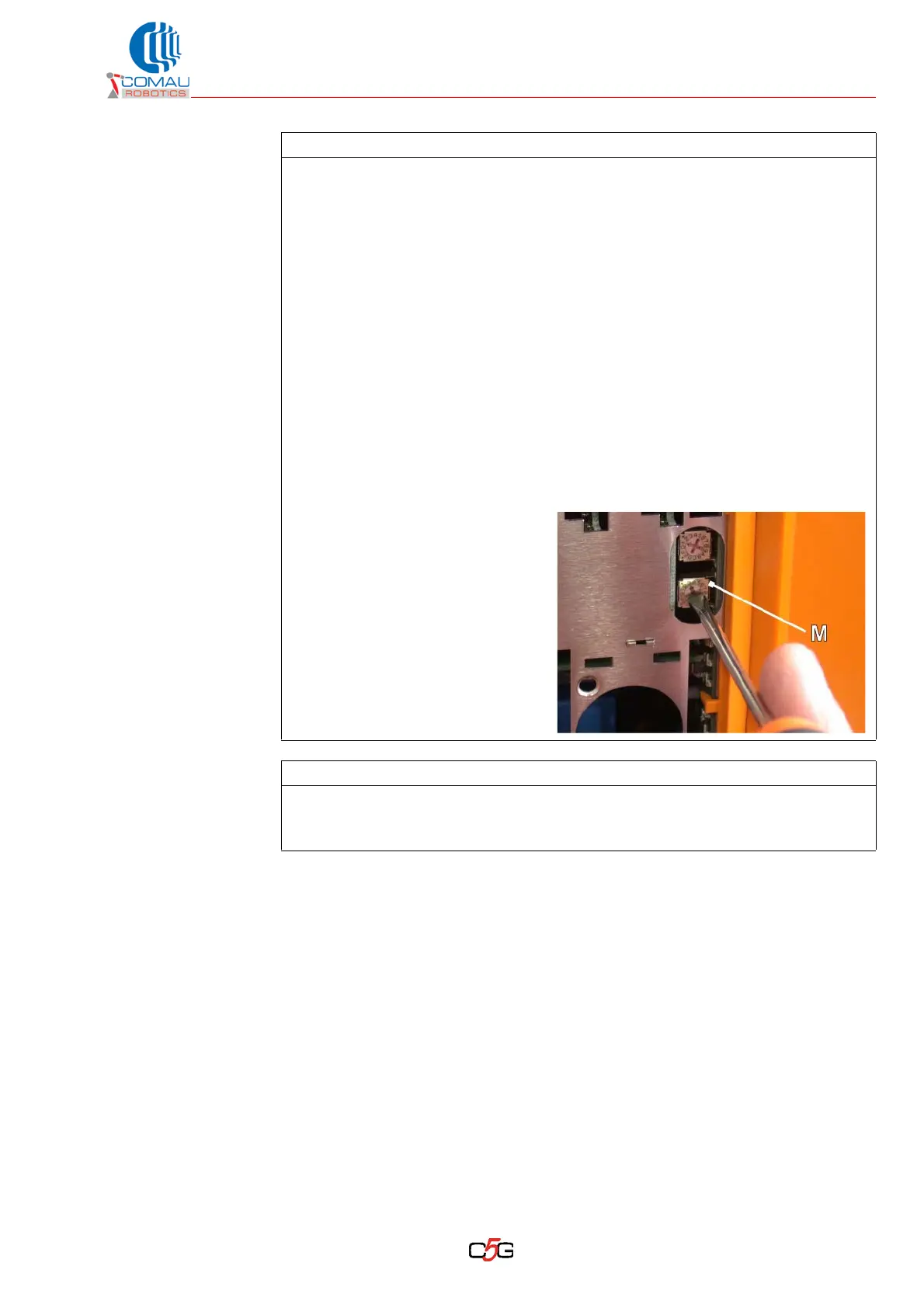
ab. Set the IP address on the
rotating selector switches (M) of
module AMS-IAM according to
the values in the removed
module.
ac. Close back the door (L).
Follow-up procedure
– Do not stand under the Robot or in the areas nearby.
– Carry out some motion cycles at reduced speed to check the proper operating.
– Select the AUTO mode and check the proper operating at reduced speed.
Operating procedure (Continued)