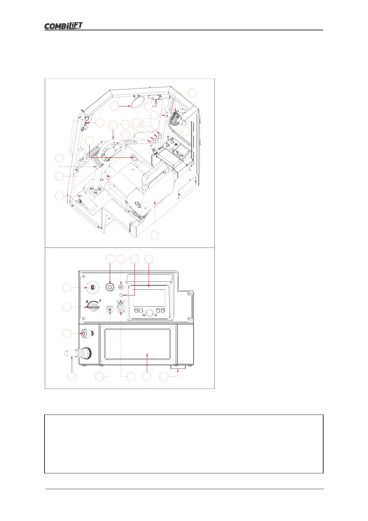
Components & Controls
28
C3M2-OM-EN-02
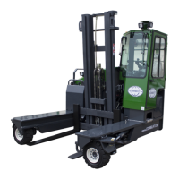
Note
The layout of the controls displayed above applies only to a standard truck.
The actual layout may vary depending on individual customer requirements.
Refer to the decals in the cabin of the individual truck if the layout is not
standard.
3.2 Operating Components & Controls
The controls and user adjustable components located inside the cabin of the truck
are labelled in figure 3.2 below.
Figure 3.2 Controls Layout
Controls
1. Steering Wheel
2. Adjustable Steering Column
3. Accelerator Pedal
4. Inch Brake Pedal
5. Operator’s Seat
6. Heater Temperature Control *
7. Operator’s Cooling Fan
8. Windscreen Wiper Switch
9. Convex Mirror *
10. Adjustable Air Vent *
11. Lift Control Lever
12. Reach Control Lever
13. Tilt Control Lever
14. Auxiliary Function Control Lever
15. RH Side Window Opener
16. Park Brake Switch
17. Ignition Key Switch
18. Horn Push Button
19. Four-Way Direction Switch
20. Heater Fan Switch *
21. Operator’s Cooling Fan Switch
22. Armrest
23. Fusebox
24. Multifunction Display Console
25. MIL Light *
26. Programming Port
27. Drive/Lift Cut-Out Override *
* If Fitted
1
2
3
4
5
8
8
9
15
1413
12
11
10
6
7
16
17
18
19 20 21
22
23
2627 25 24
3
1
2
0