Rev/Rev
Descrizione Modifiche/Change description
Emissione/Emission Approvato/Approval
-
-
Il presente disegno non può essere utilizzato né riprodotto o reso noto a terzi senza autorizzazione della Think Water
This draw cannot be used nor reproduced or given to third parts without the authorisation from Think Water
Scala/Scale
Tolleraza Generale/
General Tollerance
Denominazione/Product name
Progettista/Designer Verifica/Confirm
Codice prodotto/ Product code
Applicazione/Application
N° disegno/N°drawing
• Esecutivo/
Executive
• Sperimentale/
Experimental
Data/Date
N° tavola/N° table
Materiale/Material
1:2
-
2010
-
media 1 di 1
pavan -
Raggi non quotati/
Rays not quoted
±0.05
da/from
0.5
fino a/to
3
Designazione/
Specification
media
Denominazione/
Name
f fine
m
±0.2
±0.1
±0.1±0.1
±0.05
±0.3 ±0.5
±0.15 ±0.2
±0.8 ±1.2
±0.3 ±0.5
da/from
0.5
fino a /to
3
±0.2
1)
±0.5
±1
1) Per le dimensioni nominali minori di 0.5 [mm], gli scostamenti devono essere indicati vicino alle dimensioni nominali
1) If the nominal dimension is less 0.5 [mm] the limit of tollerance must be written near the nominal dimension
Classe di tolleranza/
Tolerance class
Tab. 1: Scostamenti limite [mm] ammessi per dimensioni lineari,
esclusi smussi e raccordi per eliminazione di spigoli (vedi Tab. 2)/
Limit of tolerance [mm] for linear dimension, without groove and
half-round fillet to erase edge
1)
Tab. 3: Scostamenti limite per dimensioni
angolari in funzione dei campi di lunghezza
[mm] del lato più corto dell'angolo/ Limit of
tolerance for angle, reference to the shorter
side of the angle [mm]
±1° ±0°30' ±0°20' ±0°10' ±0°5'
da/from
3
fino a/to
6
da/from
6
fino a/to
30
da/from
30
fino a/to
120
da/from
120
fino a/to
400
da/from
400
fino a/to
1000
da/from
1000
fino a/to
2000
da/from
3
fino a /to
6
oltre/over
6
Tab. 2: Scostamenti limite [mm] per
smussi e raccordi per eliminazione di
spigoli/ Limit of tolerance [mm] for groove
and half-round fillet to erase edge
da/from
0
fino a /to
10
da/from
10
fino a /to
50
da/from
50
fino a /to
120
da/from
120
fino a /to
400
oltre/over
4000
-
- -
-
-
-
-
-
-
-
-
- -
-
A3
UNI EN ISO 22768
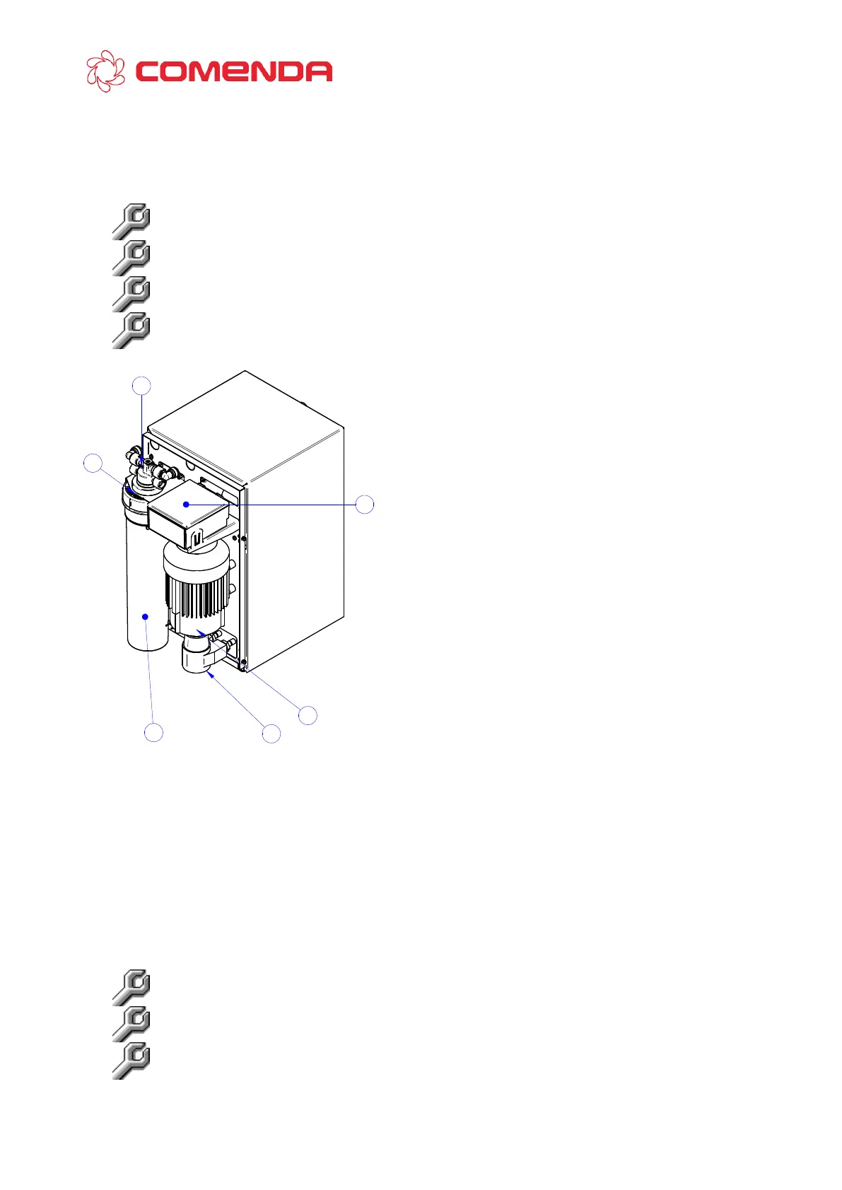
4
2
3
1
5
6
elettronica.
 Loading...