CommScope ERA
®
CAP MX Medium Power Carrier Access Point Installation Guide M0203A5A_uc
Page 42 © November 2020 CommScope, Inc.
Installing CAP MXs
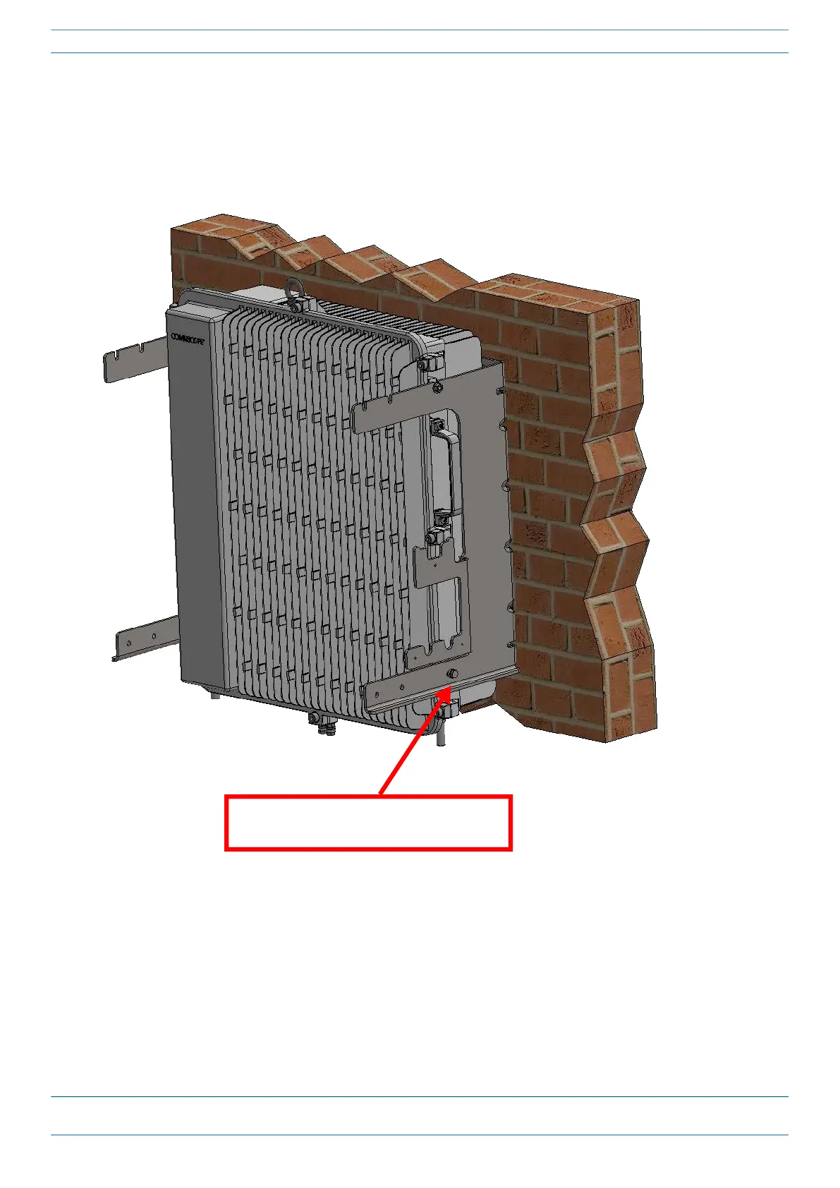
11 On lower right of the CAP MX-1, reinstall the M6x12 screw and its washers that you removed in Step 7 on
page 40.
a Slide first the M6 split-lock washer and then the M6 plain washer over the M6x12 screw.
b Insert the M6x12 screw through the screw hole shown below, and screw it back into the CAP MX-1
chassis; torque to 11 N-m (100 in-lbs).
12 Repeat Step 11 on the left side of the CAP MX-1.
M6x12 bolt and washer set in hole
closest to mounting surface