Do you have a question about the CommScope Node AM4 and is the answer not in the manual?
Lists and defines technical terms and acronyms used in the manual.
Provides crucial safety warnings and precautions for electrical hazards and radiation.
Details warnings to prevent damage to equipment or property during operation.
Outlines regulatory compliance requirements, including FCC and European standards.
Provides background information on CommScope and its product offerings.
Lists contact information for customer support across various global regions.
Explains the function of wireless communication repeaters and the Node AM4.
Describes the features and capabilities of the Node AM4 repeater unit.
Provides a step-by-step guide for initial setup and optimization of the Node AM.
Covers safety and warnings related to the physical installation of the unit.
Details the procedure for removing the protective cover before installation.
Explains how to mount the Node AM4 unit into a standard 19-inch rack.
Guides on how to install RF cards into the Node AM unit, including precautions.
Provides guidance and warnings for electrical connections.
Safety precautions for electrical installation to prevent injury or damage.
Warnings to prevent property damage during electrical installation.
Provides the procedure for grounding the unit to ensure safety and proper operation.
Details how to connect cables between internal components and RF cards.
Explains how to connect antenna cables to the unit, considering connector types.
Outlines the steps for cleaning RF cable connectors to ensure good performance.
Details the correct procedure for assembling antenna cable connectors.
Explains how to connect the power supply to the Node AM unit.
Guides on connecting the Node AM to a PC for setup and monitoring.
Step-by-step instructions for establishing a local Ethernet connection to the Node AM.
Briefly describes the process for setting up a remote connection via modem.
Explains the internal signal flow and architecture of the Node AM4 repeater.
Lists and describes the key features of the Node AM4 repeater.
Details the functionality and configuration of digital channel filters.
Describes the repeater's support for frequency hopping in GSM networks.
Explains different filter types available and their future implementation.
Details how to access and interpret status and report information.
Explains how to configure and use the alarm forwarding features.
Introduces the main hardware components of the Node AM4 system.
Describes the function and examples of the multiband combiner.
Explains the function and types of Digital Channel Modules (RF cards).
Describes the dummy card and its purpose for airflow and IP class.
Details the power supply unit specifications and types.
Explains the functions and purpose of the UI1 board.
Describes the function and configuration of external alarm inputs.
Explains the summary alarm relay and its configuration.
Introduces the UI2 board and its optional features like VSWR, Battery Backup, Modem.
Describes the VSWR module for monitoring signal reflection.
Explains the function of the battery backup unit for power failure.
Lists supported modem types and their general usage for remote connection.
Provides general maintenance recommendations and warnings.
Introduces the concept of Field Replaceable Units (FRUs) for maintenance.
Details the procedure for removing and replacing the multiband combiner.
Guides on replacing the modem or battery, including safety warnings.
Details the procedure for replacing the VSWR module.
Explains the function and interpretation of the status LED.
Guides on replacing the power supply unit, including safety precautions.
Provides instructions for replacing or adding RF cards, including warnings.
Details procedures for fan unit maintenance and replacement.
Details the procedure for replacing the backside type fan unit.
Guides on accessing and replacing the bottom type fan unit.
Presents technical drawings of the Node AM cabinet.
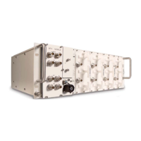
Shows a visual layout of the Node AM4 unit.
Details electrical parameters and options for RF cards.
Lists electrical specifications for various RF card options.
Details available bandwidths and filter resources for single-band cards.
Details available bandwidths and filter resources for dual-band cards.
Lists the physical dimensions and weight of the Node AM4 unit and cards.
Specifies operating temperature, ingress protection, and noise levels.
Summarizes key features like statistic collection, gain trailing, and access methods.
Lists specifications for various modem types supported by the Node AM.
Lists specifications for various modem types supported by the Node AM.
Lists specifications for the MIDGE wireless router.
| Model | AM4 |
|---|---|
| Power Supply | 90-264 VAC, 50/60 Hz |
| Operating Temperature | -40°C to +60°C (-40°F to +140°F) |
| Operating Wavelength | 1310 nm or 1550 nm |
| Return Path Gain | 28 dB (typical) |
| Housing | Aluminum |
| Dimensions | 15.5 in x 12.0 in x 6.0 in (39.4 cm x 30.5 cm x 15.2 cm) |