7. Specifications
MF0121ACP_uc.docx Manual for Node AM4 Page 75
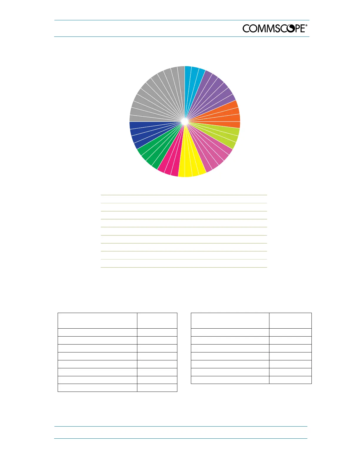
Example of filter resources allocation (up to 5 MHz wide) of Node AM4 rack (single-
band cards):
∆
Operator A GSM 900 1 Band 6 MHz
∆
Operator A GSM 1800 1 Band 32 MHz
∆
Operator A UMTS 2100 1 Band 20 MHz
∆
Operator B GSM 900 1 Band 14 MHz
∆
Operator B GSM 1800 1 Band 23 MHz
∆
Operator B UMTS 2100 1 Band 20 MHz
∆
Operator C GSM 900 1 Band 15 MHz
∆
Operator C GSM 1800 1 Band 20 MHz
∆
Operator C UMTS 2100 1 Band 20 MHz
∆
Unused filter resources: 12
table 7-5 Filter resources allocation (up to 5 MHz wide), example
All data is subject to change without notice.
7.1.3. Bandwidths available in UL and DL per dual-band card
Sub-Band Bandwidth
[MHz
Filter
Resources
Sub-Band Bandwidth
[MHz]
Filter
Resources
0.01 to 5.00 1 40.01 to 45.00 9
5.01 to 10.00 2 45.01 to 50.00 10
10.01 to 15.00 3 50.01 to 55.00 11
15.01 to 20.00 4 55.01 to 60.00 12
20.01 to 25.00 5 60.01 to 65.00 13
25.01 to 30.00 6 65.01 to 70.00 14
30.01 to 35.00 7 70.01 to 75.00 15
35.01 to 40.00 8
table 7-6 Bandwidths available in UL and DL per dual-band card
All data is subject to change without notice.
3
4
5
6
7
8
9
10
11
12
13
14
15
16
17
18
19
20
21
22
23
24
25
26
27
28
29
30
31
32
33
34
35
36
37
38
39
40
41
42
43
44
45
46
47
48
2
1