4. Functional Description
MF0121ACP_uc.docx Manual for Node AM4 Page 45
Pin 4
Pin 6
Pin 5
The following table describes the three-connector PIN out.
Pin No. Contact Maximum Resistive Load
4 Open in normal condition
Max. 0.5 A @ 60 VDC
5 Common
6 Closed in normal condition
table 4-1 Pin assignment of relay contacts
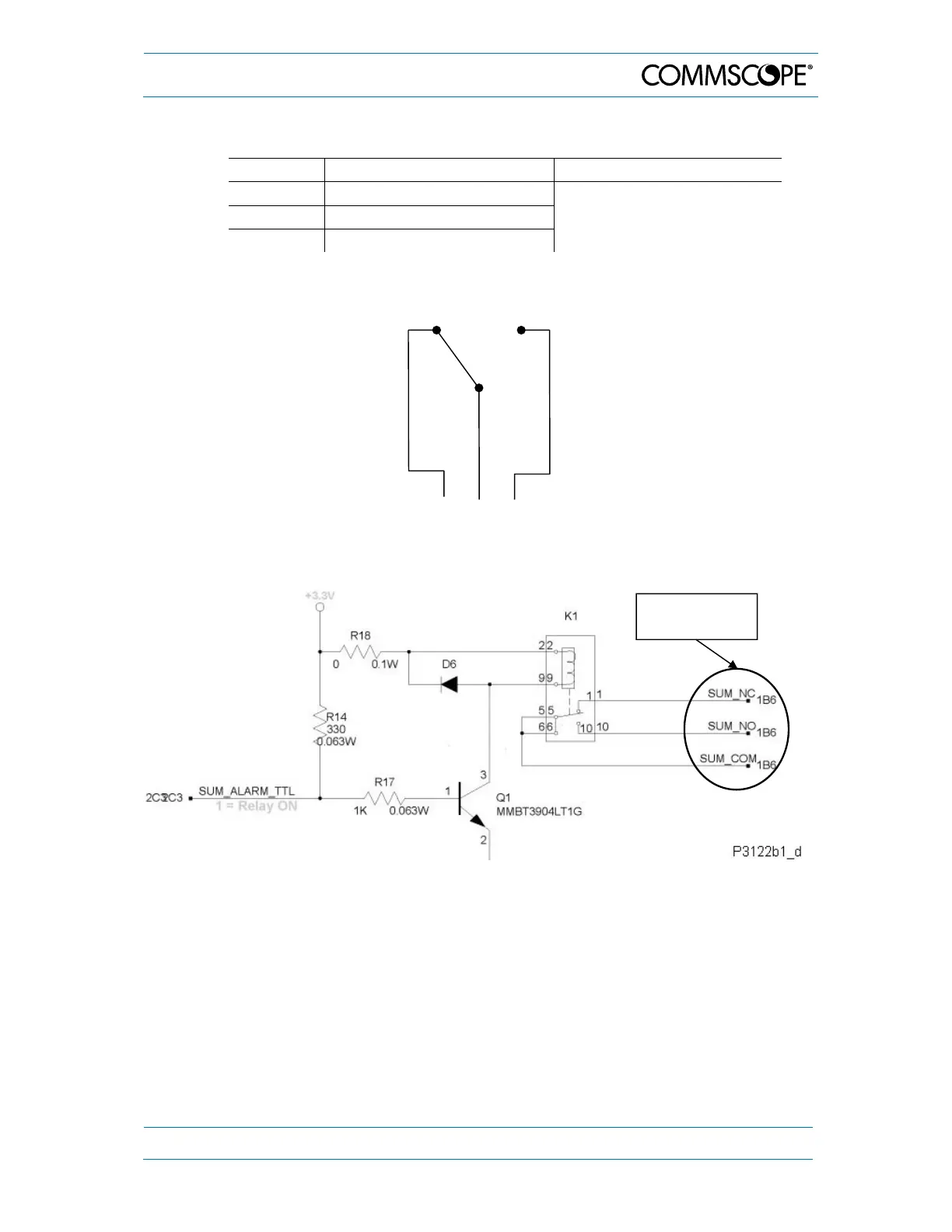
figure 4-14 Relay contacts, alarm condition
figure 4-15 Schematics of summary alarm clamps
Summary
alarm clamps