4. Functional Description
Page 42 MF0121ACP_uc.docx Manual for Node AM4
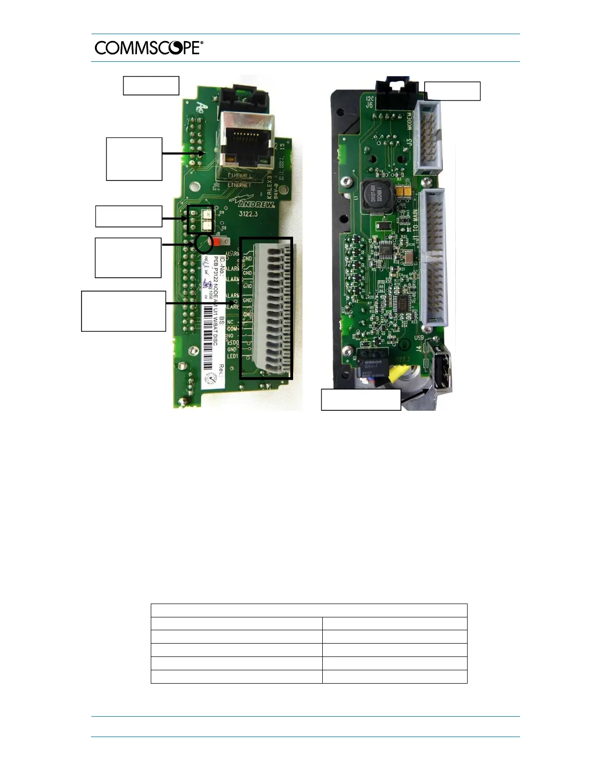
figure 4-9 UI-board for general applications, top and rear view
4.3.5.1. External Alarms
The external alarms are used to monitor the status of one or more external devices via
the Node AM. A UPS or entry alarm is among the items that might be connected to the
contact relay and monitored via the Node AM4. The cage clamp connectors are located
on the UI1-board.
Observe that the cross-sectional area of the wires to be connected must be in the range
from 0.4 - 0.8 mm
2
(AWG 26-20). Do not use wire-end sleeves.
All external alarms are defaulted to high (3.3V TTL) without connection. This setting may
be changed on the external alarm page to active high or active low. The severity levels of
the external alarms may be set via the web page. More information about the external
alarm settings is available in the web page and online help.
External Alarms 1 to 5
Input volta
e ran
e 0 to 5 Vdc
Recommended input line Potential free
Nominal sink current to ground 15 m
ctive level High or low set via software
Connectors Cage clamps
External alarm &
summary alarm
terminal block
Top view
Rear view
USB connector
Battery
disconnect
push-button
Local
Ethernet
connector
Status LEDs