3. Installation
MF0121ACP_uc.docx Manual for Node AM4 Page 31
3.2.8. Power Connection
Before connecting electrical power to the unit, the system must be grounded (earthed) as
described in chapter 3.2.3 and connected via external circuit breaker (see table 3-3).
Mains power must be connected at the mains connector. The mains cable (assembled
feed line) is included in the Node AM4.
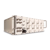
The PIN assignment of the mains connector is as follows:
figure 3-4 DC Mains connector, PIN
assignment
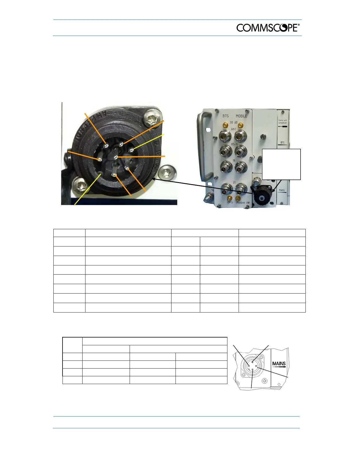
figure 3-5 Mains connector, location
Mains DC connector Mains cable 1* Mains cable 2**
PIN Connection Color Marking Color
1 +V DC grey 1 red
2 +V DC grey 1 red
3 +V DC grey 1 red
4 not connected --- --- ---
5 -V DC grey 2 black
6 -V DC grey 2 black
Center -V DC grey 2 black
* Grey marking 2 is always the negative potential, grey marking 1 is the positive one.
** Black is always the negative potential while red is the positive one.
PIN
AC Mains Connector
Connection Colo
1 Phase brown black
2 Neutral blue white
3 not connected - --
4 PE green / yellow green
table 3-2 AC Mains connector, PIN assignment
Mains
Connector
(remove
cover)
Center
PIN 6
PIN 1
PIN 3
PIN 2
(PIN 4
n.c.)
PIN 5
Stud
PIN 6
PIN 1
PIN 2
PIN