4. Functional Description
Page 38 MF0121ACP_uc.docx Manual for Node AM4
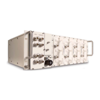
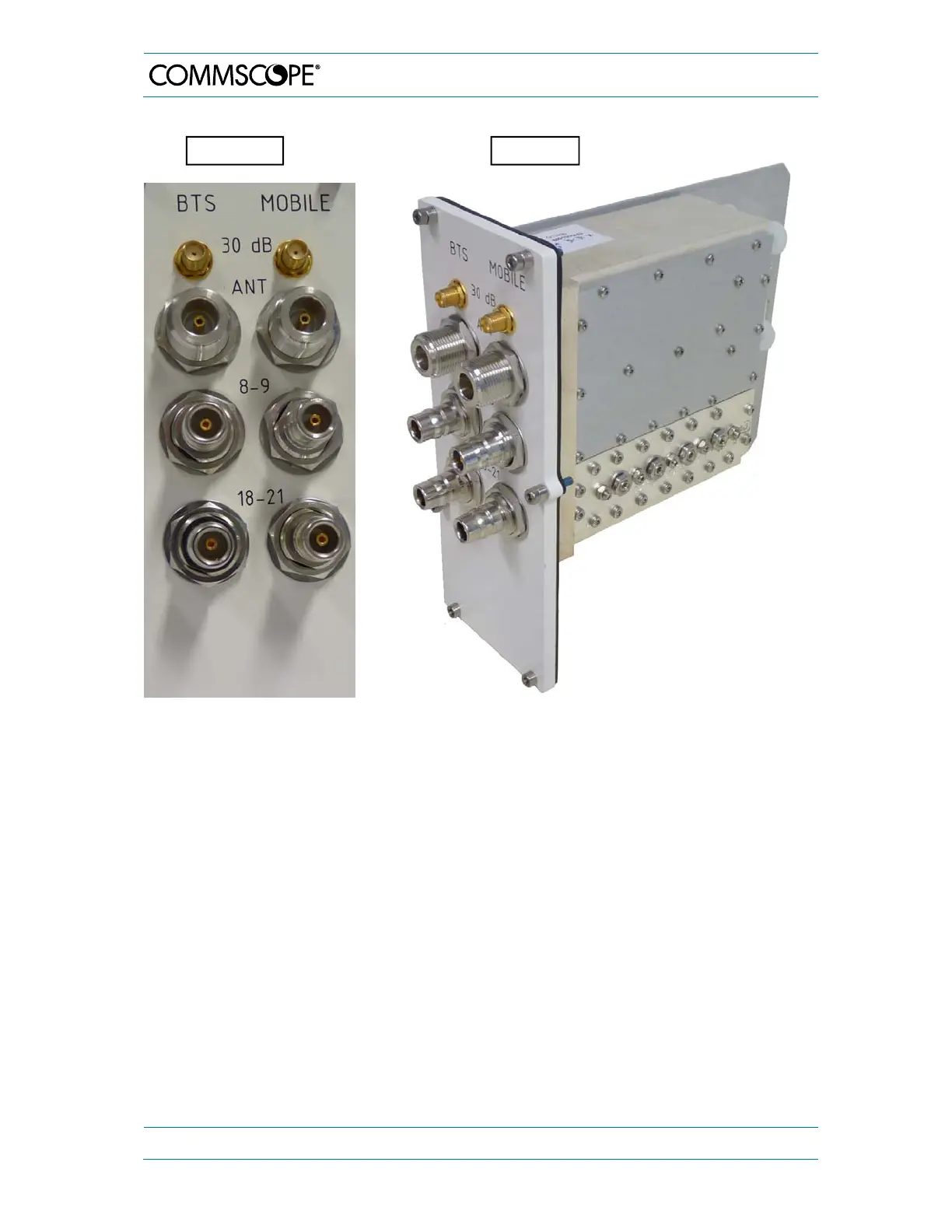
figure 4-3 Node AM4 2-band combiner (800-900 and 1800-2100 MHz) with two pairs of
band ports
Via an additional external 10 dB directional coupler the modem can be connected using
the direct Modem RF port [1]. In case an external 10 dB directional coupler cannot be
used, an integrated directional probe (QMA connector at the rear side of the combiner;
see also figure 4-19) may be used to supply the modem with RF signals. :
Further optional ports of the combiner are the GPS port [2] with optional GPS LNA DC
supply (for the corresponding connections on the rear side see also figure 4-19) as well
as two 30 dB coupling probes [3], which can be used for testing purposes for the antenna
ports.
Front vie
3-D-view