5. Maintenance
MF0121ACP_uc.docx Manual for Node AM4 Page 61
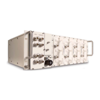
5.2.3. VSWR Module (Optional)
The VSWR module is located on top of the modem plate. For removing and inserting the
plate, refer to chapter 5.2.2.
figure 5-2 VSWR module, layout
To replace the optional VSWR module, proceed in the following order:
Unscrew the two M3x10 counter-sunk head screws underneath the rear side of the
modem plate.
Cutting the cable tie is not necessary if you carefully disconnect the USB
connectors and RF cables before taking out the module.
Note: Make sure to remember their correct positions according to the
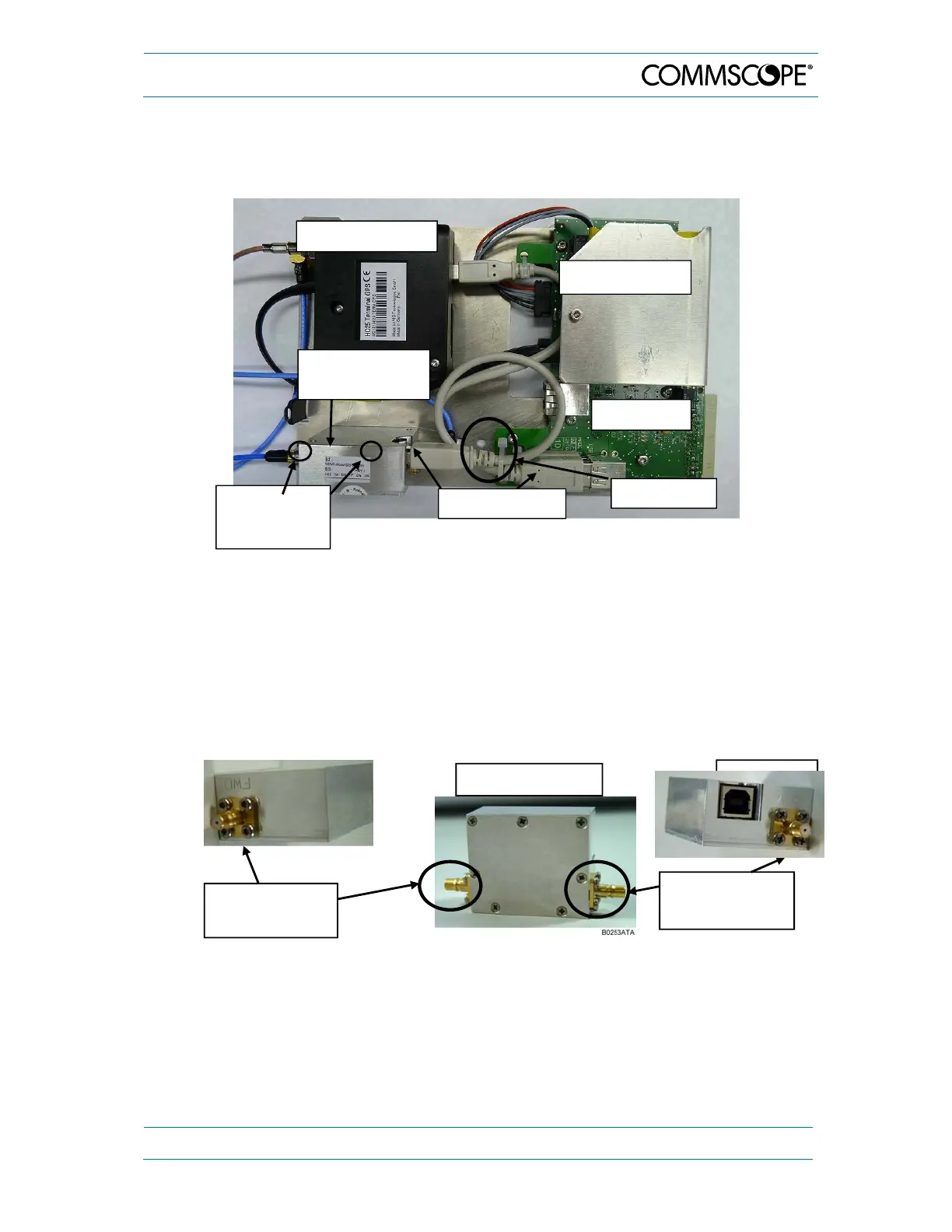
RF connectors labeled with FWD (Abbrev. for FORWARD - left) and
REV (Abbrev. for REVERSE - right), see following illustrations:
figure 5-3 VSWR module, position of RF connectors
Insert the new VSWR module and proceed in reverse order, i.e. fasten the two
screws again from below and reconnect the USB and RF cables.
Note: Be careful with the RF connectors! Do not confuse REV and FWD
connectors! Ensure to re-connect the FWD-RF connector and cable to
their correct positions before the replacement, (as illustrated in figure
5-3 VSWR module, position of RF connectors).
Two M3x10
screws
underneath
RF connector
"FWD"
RF connector
"REV"
VSWR module
USB connector
UI2 board
Optional BBU
Cable tie
VSWR module
(optional)
Optional modem