5. Maintenance
Page 60 MF0121ACP_uc.docx Manual for Node AM4
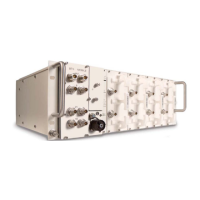
Screw the new
modem to the
carrier plate with
the two hexagon
socket-head-cap
screws M3x30.
Insert the carrier
plate of the
modem into the
guide rails and
carefully push it
in, however not
completely.
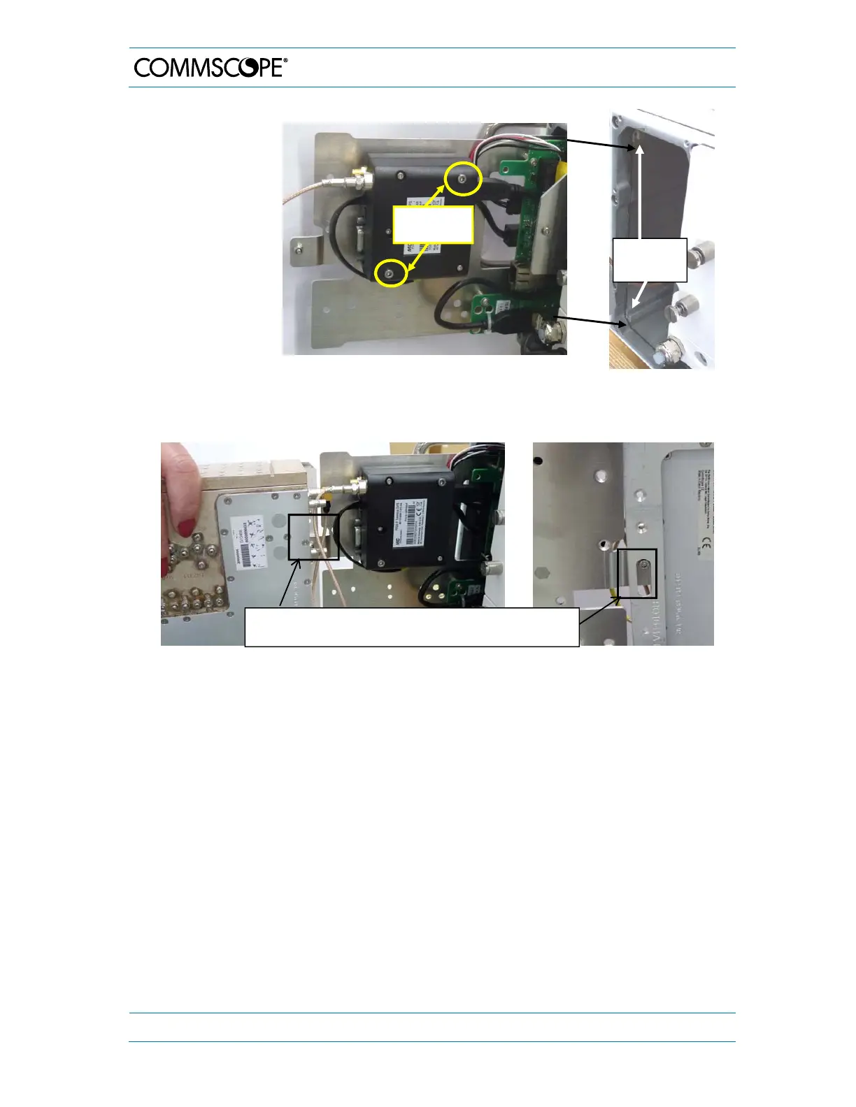
First, reconnect all cables between combiner and modem. Then, reconnect the combiner
and modem carrier plates by hooking the screw of the modem mounting plate into the
long hole of the combiner plate:
For the final installation of both, refer to the explanation in chapter 5.2.1, strictly observing
the corresponding warning messages.
Guide
rails
Mounting plates of combiner and modem connected by
screw locked into lon
hole
seen from both sides
.
2 screws
M3x30