4. Functional Description
Page 50 MF0121ACP_uc.docx Manual for Node AM4
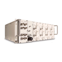
Connect the wires, cables and connectors of the MC88 / TRM-5 modem kit according to
the following wiring illustration:
figure 4-21 Modem Kit MC88/TRM-5 Node AM, schematic wiring
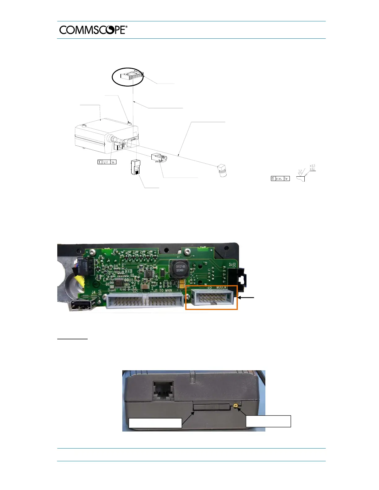
figure 4-22 UI1 Board, position of modem RS232 connector
SIM Card
To insert the SIM card, use a pen and press the small yellow button.
Then, the SIM-card drawer will come out and the SIM-card can be inserted.
Carefully push the drawer to its original position.
figure 4-23 SIM-card drawer
Cable AC/DC AWG26
240 mm 6-wires to UI2
Board
Cable RF RG-316 0.3 m
FME, female, straight
Ribbon-cable harness
14-wires
not used
to UI1 Board
GSM Modem Cint.
MC88-T/EGS5
M3.0x 35 mm hexagon
socket-head cap screw
All unmarked screw joints: nominal tightening
torque values according
to QA 7.5.1.090/F1011P0
Part(s) to be clean and free of all chips,
burrs, sharp edges and foreign material
G3266M379
-
Yellow button
* Connector on UI1 Board for
RS232 cable to
MC88/TRM-5 modems
* for position on UI1 Board see figure 4-22