3. Installation
MF0121ACP_uc.docx Manual for Node AM4 Page 25
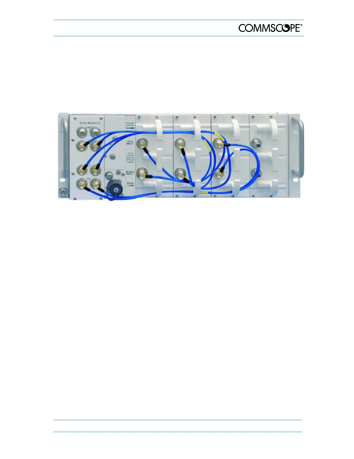
3.2.4. Interconnection Cabling
The required cables are part of the delivery of the RF cards.
Connect the individual BTS band ports of the combiner (if equipped) to the BTS ports of
the according band of the RF cards.
Connect the individual Mobile band ports of the combiner (if equipped) to the Mobile ports
of the according band of the RF cards.
However, the antennas may also be mounted directly on the RF card connectors.
figure 3-2 Example for interconnecting cabling for a Node AM4 (combiner with three
pairs of band ports)
3.2.5. Connection of the Antenna Cables
The antenna connectors of the Node AM combiner are N female. However, the antennas
may also be mounted directly on the RF card connectors which are QN. All connectors
are located at the front of the cabinet.
An operator should refer to the documentation of the cable connector manufacturer for
best mating procedures. Furthermore, the bending radius of the antenna cables should
be maintained at all times.
There are several issues to be considered when selecting the cable and antenna types.
In applications such as trains and ferries, it is highly recommended to use
directional antennas with good front-back-ratios (40 dB is typical) because they
improve isolation and cell-site selectivity.
Smaller diameter cables are less expensive and easier to install but have worse
performance.