7. Specifications
Page 74 MF0121ACP_uc.docx Manual for Node AM4
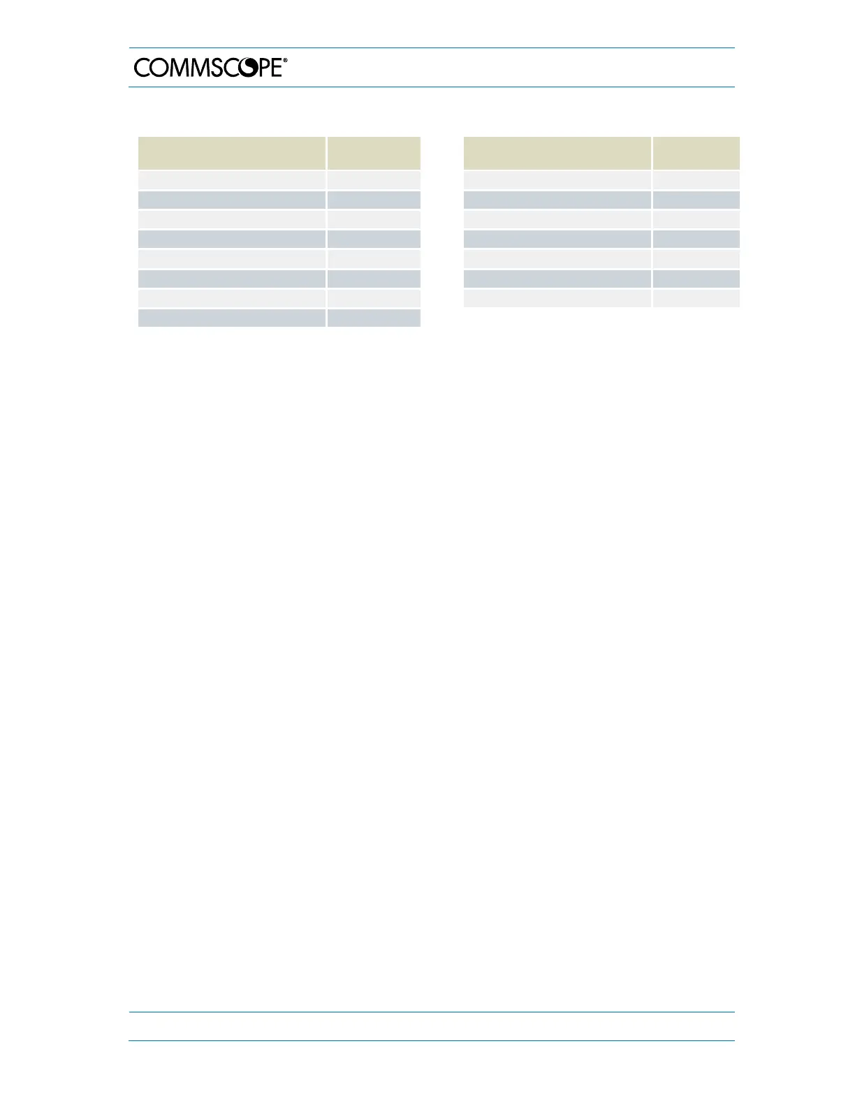
7.1.2. Bandwidths available in UL and DL per rack (single-band cards)
Sub-Band Bandwidth [MHz] Filter
Resources
Sub-Band Bandwidth [MHz] Filter
Resources
0.01 to 5.00 1
40.01 to 45.00 9
5.01 to 10.00 2
45.01 to 50.00 10
10.01 to 15.00 3
50.01 to 55.00 11
15.01 to 20.00 4
55.01 to 60.00 12
20.01 to 25.00 5
60.01 to 65.00 13
25.01 to 30.00 6
65.01 to 70.00 14
30.01 to 35.00 7
70.01 to 75.00 15
35.01 to 40.00 8
table 7-4 Bandwidths available in UL and DL per rack, single-band cards
All data is subject to change without notice.
Detailed System Description – Single-Band Cards
Node AM RF cards convert the RF into digital signals and transfer them to the Node AM
rack for digital filtering. The digital architecture allows sub-band filtering and is shared
between all RF Cards inserted into the Node AM rack. The Node AM4 can provide up to
48 filter resources (up to 5 MHz each). Additional filtering capability is provided by on-
card digital signal processing at dual-band RF cards to satisfy increasing demand of sub-
bands for further RF-bands or MIMO deployments. When the sub-band bandwidths are
greater than 5 MHz, the filter resources are grouped together, without phase or amplitude
ripple, where the sub-band is defined by a start and stop frequency. The total number of
used filter resources is determined by adding the number of filter resources required for
each sub-band.
For example, if there are three sub-bands with 4 MHz for the first sub-band, 11 MHz for
the second sub-band, and 20 MHz for the third sub-band, then 1 filter resource is required
for the first sub-band, 3 filter resources are required for the second sub-band and 4 filter
resources are required for the third sub-band. The total number of used filter resources
in this example is 8. However, the maximum available bandwidth (240 MHz) will only be
achieved with sub-band bandwidths of integer multiple of 5 MHz.
The following diagram shows examples for filter resources allocation: