JHT01 Service Manual
5-23
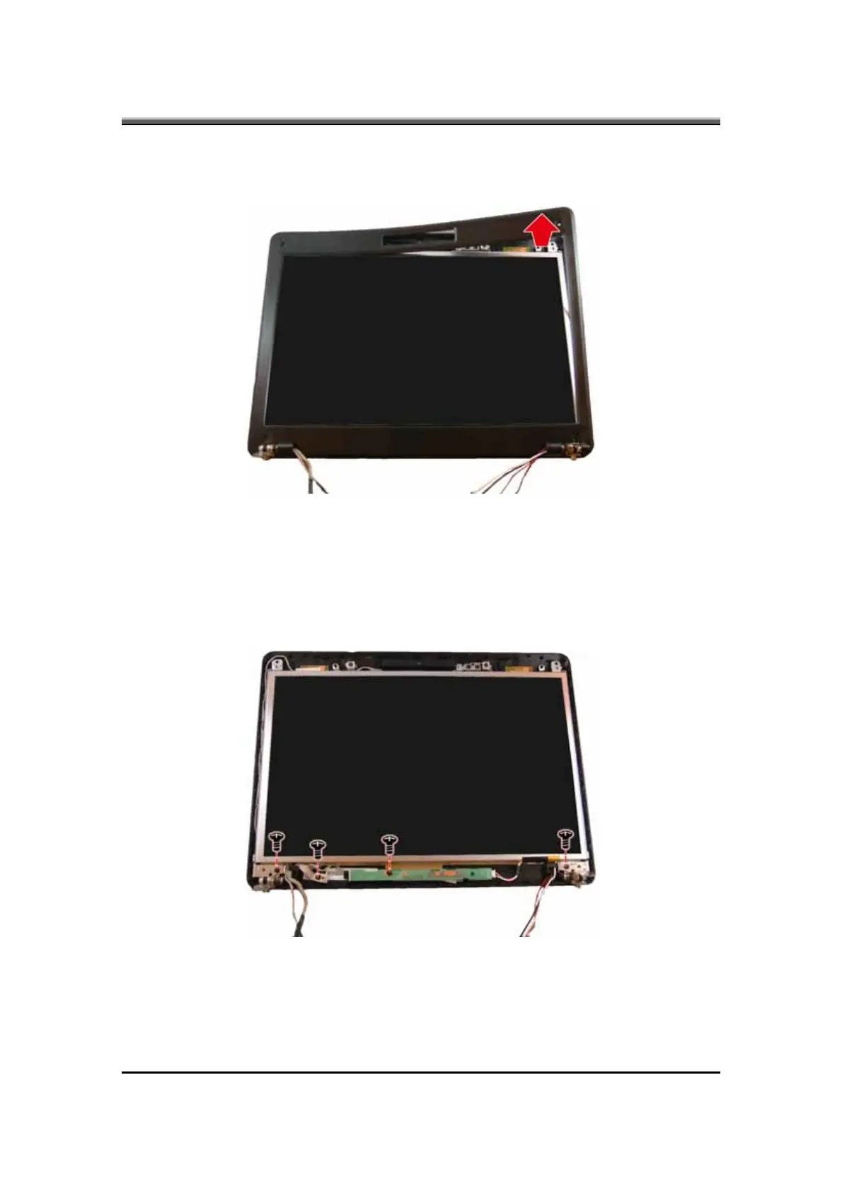
3. Carefully insert your fingers between the display and the LCD bezel as
indicated by the arrow, and gently pry up the LCD bezel.
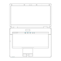
4. Remove the four screws mounting the display, inverter board, and
LVDS/CMOS cable to the LCD cover.
• Two screws on the display.
•
Two screws on the inverter board.
• One screw on the LVDS/CMOS cable.