JHT01 Service Manual
6-6
The power supply controls many functions and components. To determine if the
power supply is functioning properly, start with Procedure 1 and continue with
the other Procedures as instructed. The flowchart in Figure 6-2 gives a summary
of the process.
The procedures described in this section are:
• Procedure 1: Power status check
• Procedure 2: Adaptor / battery replacement
• Procedure 3: Power supply connection check
•
Procedure 4: Diagnostic check
• Procedure 5: Internal connection check
3.1 Procedure 1 Power Status Check
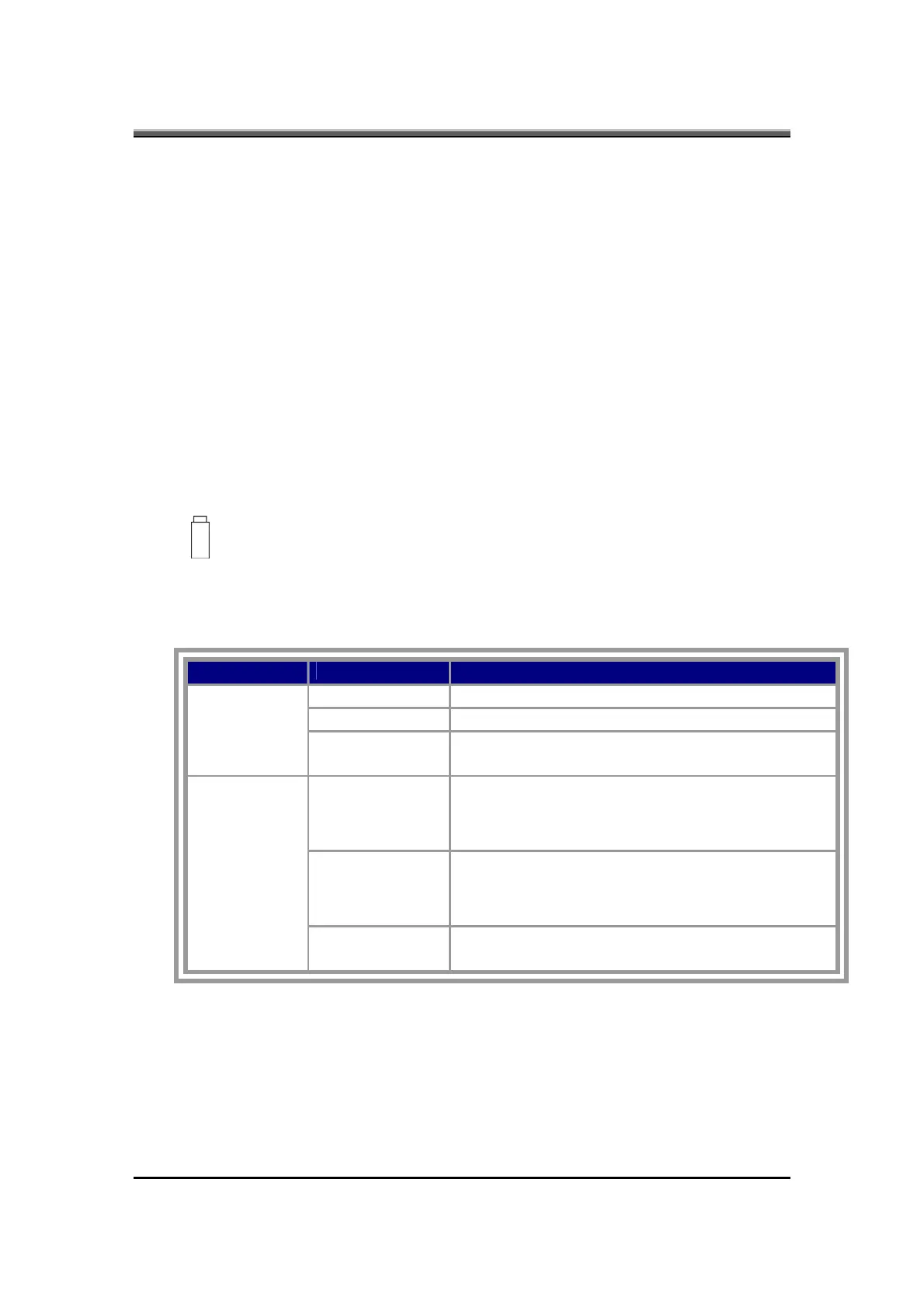
The following LEDs indicate the power supply status:
Battery LED
The power supply controller displays the power supply status through the Battery
and the POWER LEDs as listed in the tables below.
Table 2-1 Battery LED
Battery State LED colors Definition
blue, blinking Battery charging with AC
blue, solid on Battery fully charged by AC
Charging
color off Battery abnormal: stop charging with AC
(Bad cell/ Overheated)
Amber, blinking
LED on for 1
second every 4
seconds
Battery within low state: 12 minutes remaining
Amber, blinking
(LED on 1
second every 2
seconds)
Battery within critical low state: 3 minutes remaining.
The system is protected and cannot be re-powered
on without the AC power connected.
Discharging
Color off Battery not in low or critical low state; in discharging
state