JHT01 Service Manual
4-14
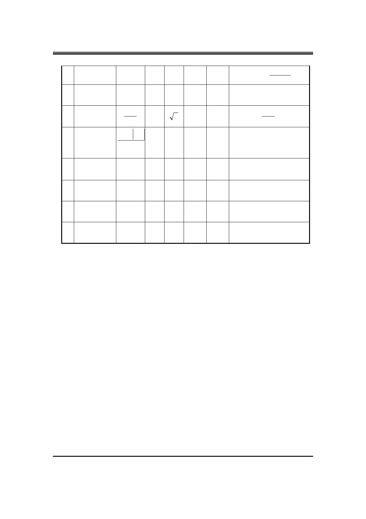
30 -- 100 %
Period
Ton
Duty =
13
Lamp current
over-shoot
-- 10 %
Line transient (10.8V to
21V/100us) and turn on
transient
14
Current
Waveform
factor
rms
p
I
I
1.27
2
1.56 Multiple
OR
rms
p
I
I
−
*10
15
Unbalance
Rate
rms
pp
I
II
−
−
-10% 0 +10% Multiple
16
Turn off
current
(Hight side)
IHL -- -- 0 A PWM=30%
17
Turn off
voltage
(Low side)
Voff -- --
150Vp-
p
V PWM=30%
18
Voltage Rise
time (Low
side)
Trise -- -- 300us Us PWM=30%
19
Voltage fall
time (Low
side)
Tfall -- -- 300us Us PWM=30%
Notes:
•
The inverter can work in 7.5V input voltae (continuous), but 7.5V electronic
characteristic will not be care. (Note: the display must be normal and can not
glitter or become dark)
•
Limited lamp maximum current by DAC_BRIG signal:
When DAC_BRIG voltage is 0V and INV_PWM enables (100%), lamp has
max.-limited current.
When DAC_BRIG voltage is 3.3V and INV_PWM enables (100%), lamp has
min.-limited current.
When add 1V DAC, the 100% Lamp current will decrease 0.5mA.
DAC_BRIG signal comes from system chipset with internal resistance of 3KΩ.
• Inverter operating frequency should be within specification (45~65kHz) at
max. and min. brightness load.
•
INV_PWM enable implies INV_PWM signal is High level (On duty cycle is
100%). It is a square wave of 150Hz to adjust backlight brightness that is a
function of PWM duty cycle. Backlight brightness is maximum value under
INV_PWM at 100% and brightness is minimum under INV_PWM at 30%.
• The system interface signals belong to 3.3V.
•
Please make sure open lamp output voltage should be within starting voltage
specification.